(3) Remove engine air inlet tube and air distribu-
tion duct for access to compressor lines.
(4) Remove bolt holding line at compressor using a
6mm allen wrench (3.2/3.5L), or M10 Hex (2.7L) (Fig.
32) and (Fig. 33).
(5) Remove line by pulling rear end of line up out
of vehicle with compressor end following through the
tie-rod area.
INSTALLATION
For installation, reverse the above procedures.
Tighten TXV and compressor fasteners to 23 N·m (17
ft. lbs.). 2.7L: Rail screw and mid-line nut to 7 N·m
(5ft. lbs.).
SUN SENSOR
REMOVAL
(1) Open hood and disconnect the negative battery
cable remote terminal from the remote battery post
(Fig. 13).
(2) Remove instrument panel top cover.
(3) Remove two Sun Sensor mounting screws.
(4) Lift sensor out of instrument panel and discon-
nect wiring.
(5) Remove sensor from vehicle.
INSTALLATION
CAUTION: The sun sensor must protrude approxi-
mately 1/4 inch above the instrument panel top
cover. This will ensure proper operation.
For installation, reverse the above procedures.
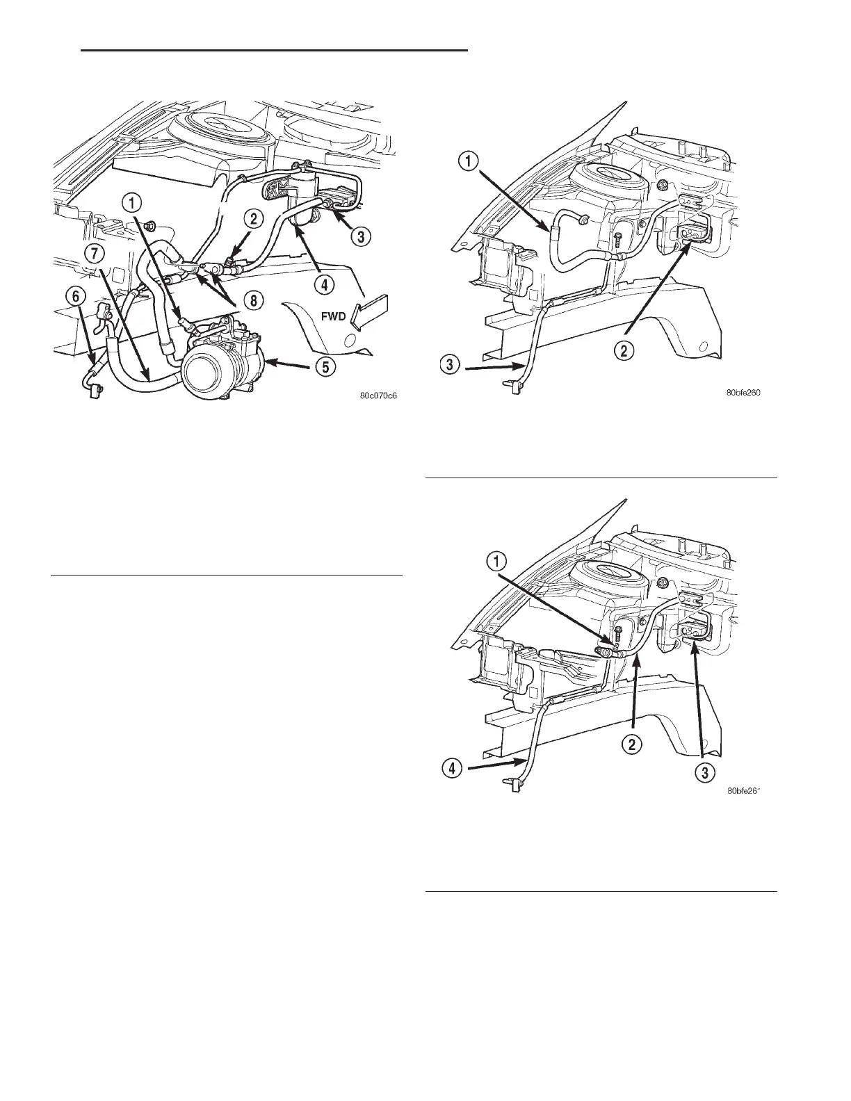
Fig. 31 A/C Refrigerant Lines and Expansion Valve
2.7L
1 – A/C PRESSURE TRANSDUCER
2 – SERVICE PORT
3 – EXPANSION VALVE
4 – FILTER-DRIER
5 – A/C COMPRESSOR
6 – LIQUID LINE
7 – DISCHARGE LINE
8 – SUCTION LINES
Fig. 32 Suction Line 3.2L/3.5L
1 – SUCTION LINE
2 – EXPANSION VALVE
3 – LIQUID LINE
Fig. 33 Suction Line 2.7L
1 – SERVICE PORT
2 – SUCTION LINE
3 – EXPANSION VALVE
4 – LIQUID LINE
LH HEATING AND AIR CONDITIONING 24 - 27
REMOVAL AND INSTALLATION (Continued)