(3) Proceed to set the front wheel alignment. If
front camber and caster readings are within required
specifications, proceed to Front Wheel Toe Adjust-
ment. If not, refer to the following procedure to cor-
rect camber.
CAMBER AND CASTER
Front wheel Camber and Caster settings on this
vehicle are determined at the time the vehicle is
designed. This is done by determining the precise
mounting location of the vehicle’s suspension compo-
nents throughout the design and assembly processes
of the vehicle. This is called a Net-Build vehicle and
results in no normal requirement for adjustment of
the Camber and Caster after a vehicle is built, or
when servicing the suspension components. Thus,
Camber and Caster are not normally considered an
adjustable specification when performing an align-
ment on this vehicle. Though Camber and Caster are
not adjustable, they should be checked during the
alignment procedure to ensure they meet the manu-
facturers specifications.
If camber and caster do not meet required specifi-
cations, the vehicles suspension components should
be inspected for any signs of damage or bending.
This inspection must be done before perform-
ing the camber setting procedure.
If a vehicle has a drift or lead condition, and it is
determined that the drift or lead is not caused by
road conditions, the front camber can be adjusted
using the following camber adjustment procedure.
CAUTION: Do not attempt to adjust the vehicles
Caster or Camber by heating, bending or by per-
forming any other modification to the vehicle’s front
suspension components.
FRONT CAMBER ADJUSTMENT PROCEDURE
There are camber adjustment bolts and nuts avail-
able to allow front suspension camber adjustment in
the event the vehicle pulls even though the camber is
within specifications. This procedure involves replac-
ing the original strut clevis to knuckle attachment
bolts with special undersized bolts.
(1) Raise the front of vehicle by the frame until
the tires are not supporting the weight of the vehicle.
(2) Remove the tire and wheel assembly from the
location on the vehicle requiring camber adjustment.
CAUTION: When removing the strut to knuckle
bolts from the strut clevis bracket, do not allow
knuckle to pull away, putting a strain on the brake
flex hose.
CAUTION: The bolts attaching the strut to the
steering knuckle are serrated in the area where they
go through the steering knuckle and strut. When
removing, do not turn the bolts in the steering
knuckle. If bolts are turned in the steering knuckle,
damage to the steering knuckle will result.
(3) Remove the nuts from the bolts attaching the
strut to the knuckle (Fig. 6). Tap the bolts out of the
knuckle.
(4) Loosely install the camber adjustment bolts
and nuts attaching the strut to the steering knuckle.
The bolts should be installed so the nuts are towards
the front of the vehicle.
(5) Install the tire and wheel assembly.
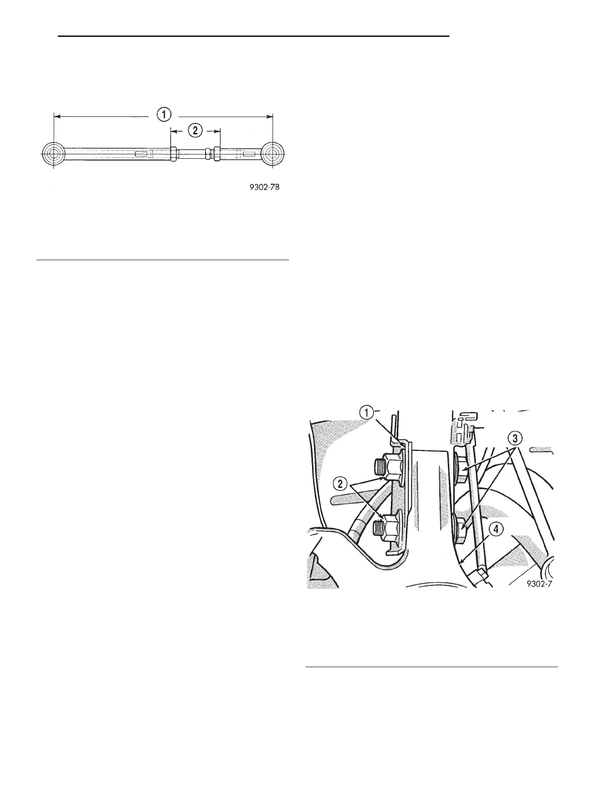
Fig. 5 Lateral Link Maximum Length Dimensions
1 – 380mm
(MAX)
2 – 90mm
(MAX)
Fig. 6 Strut To Steering Knuckle Attaching Bolts
1 – STRUT ASSEMBLY
2 – NUTS
3 – STRUT ASSEMBLY TO STEERING KNUCKLE ATTACHING
BOLTS
4 – STEERING KNUCKLE
LH SUSPENSION 2 - 7
SERVICE PROCEDURES (Continued)