tion. Then repeat the tightening sequence to the full
specified torque of 129 N·m (95 ft. lbs.).
(11) Lower vehicle to the ground.
CAUTION: When torquing hub and bearing assem-
bly to stub shaft retaining nut, do not exceed the
maximum torque of 163 N·m 6 14 N·m (120 ft. lbs.
6 10 ft. lbs.). If the maximum torque is exceeded
this may result in a failure of the drive shaft.
(12) Apply the brakes to keep the vehicle from
moving, then tighten the NEW stub axle retaining
nut to a torque of 163 N·m 6 14 N·m (120 ft. lbs. 6
10 ft. lbs.) (Fig. 27).
HUB AND BEARING (FRONT)
REMOVAL
(1) Raise vehicle on jackstands or centered on a
frame contact type hoist. See Hoisting in the Lubri-
cation and Maintenance section of this manual, for
the required lifting procedure to be used for this
vehicle.
(2) Remove the front wheel and tire assembly from
the vehicle.
(3) Remove the 2 guide pin bolts mounting the cal-
iper assembly to the steering knuckle (Fig. 28).
Remove the caliper from the front steering knuckle.
Refer to Disc Brake Caliper in the Removal And
Installation Section in the Brake Group of this ser-
vice manual for the caliper removal procedure.
(4) Remove rotor from hub by pulling it straight
off wheel mounting studs (Fig. 29).
(5) Remove the hub and bearing retaining nut
(Fig. 30).
(6) Remove the 3 hub and bearing assembly to
steering knuckle attaching bolts (Fig. 31).
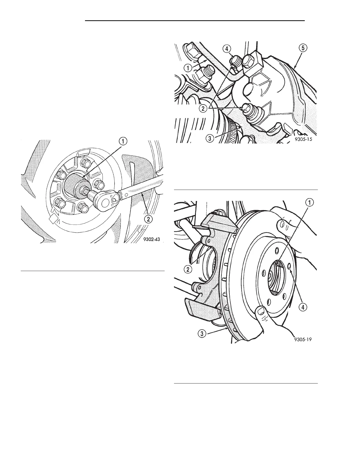
Fig. 27 Torquing Hub And Bearing Retaining Nut
1 – HUB/BEARING
2 – TORQUE WRENCH
Fig. 28 Disc Brake Caliper Mounting
1 – BRAKE LINE
2 – CALIPER GUIDE PIN BOLTS
3 – STEERING KNUCKLE
4 – BLEEDER SCREW
5 – CALIPER ASSEMBLY
Fig. 29 Removing Rotor
1 – HUB
2 – STEERING KNUCKLE
3 – BRAKING DISC (ROTOR)
4 – WHEEL MOUNTING STUD
2 - 22 SUSPENSION LH
REMOVAL AND INSTALLATION (Continued)