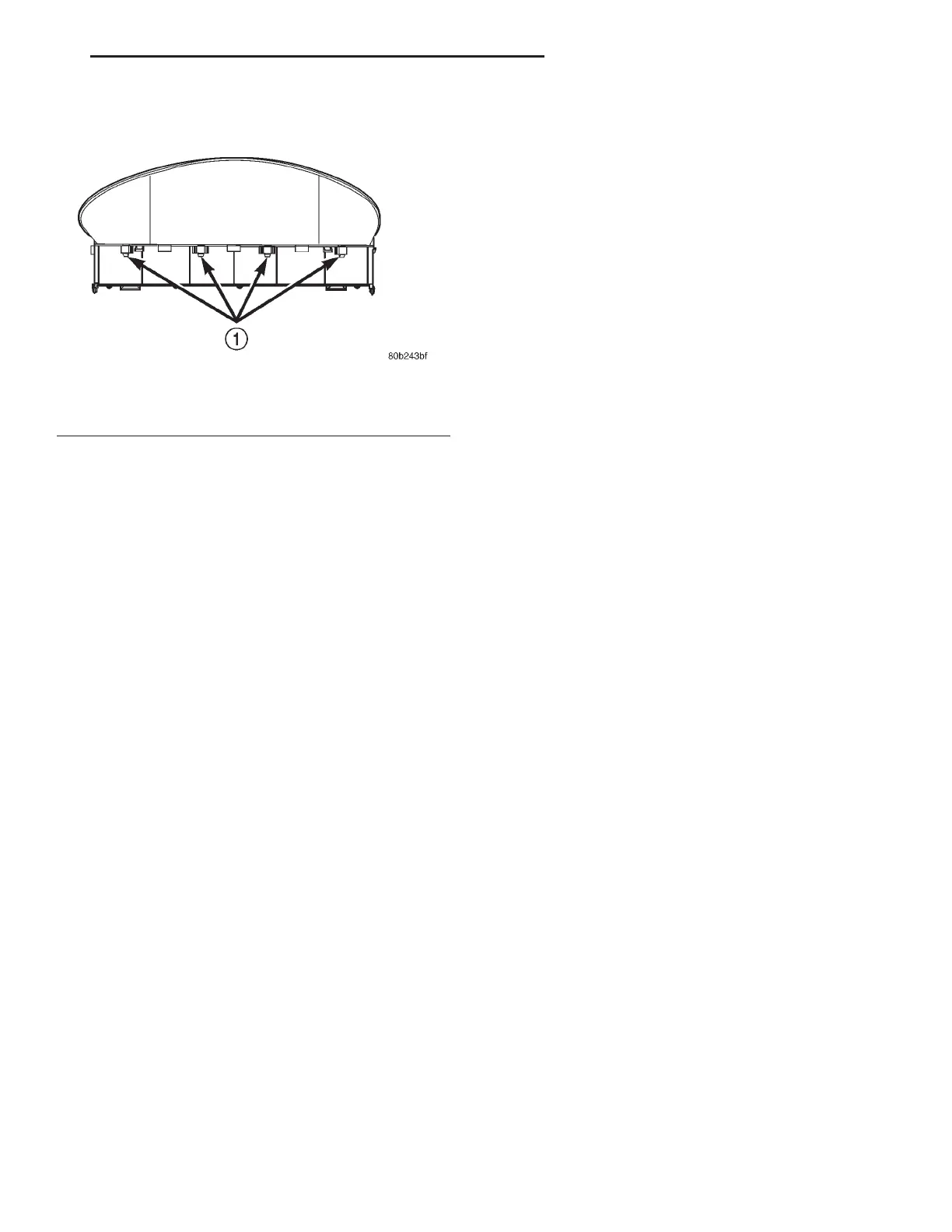
(4) Unsnap seven retaining tabs holding mask/lens
to cluster housing (Fig. 18).
(5) Separate mask/lens from instrument cluster
and remove.
INSTALLATION
For installation, reverse the above procedures.
COMBINATION FLASHER
The combination flasher is located on the left side
of the instrument panel, underneath, between the
junction block and the brake pedal.
REMOVAL
(1) Open hood and disconnect the negative battery
cable remote terminal from the remote battery post
(Fig. 22).
NOTE: It may be necessary to remove the left side
lower instrument panel cover to gain access to
Combination Flasher.
(2) Slide the Combination Flasher rearward to
remove from the electrical bracket.
INSTALLATION
For installation, reverse the above procedures.
CUBBY BIN/STORAGE COMPARTMENT
REMOVAL
(1) Open hood and disconnect the negative battery
cable remote terminal from the remote battery post
(Fig. 22).
(2) Remove ash receiver (if applicable).
(3) Using a trim stick (special tool #C-4755), gently
pry out on center trim bezel. Disconnect wiring con-
nectors to HVAC controls, cigar lighter/auxiliary
power outlet and traction control switch.
(4) Remove instrument panel center trim bezel.
(5) Remove two retaining screws to cubby bin and
remove.
INSTALLATION
For installation, reverse the above procedures
DECKLID RELEASE SWITCH
REMOVE
(1) Open hood and disconnect the negative battery
cable remote terminal from the remote battery post
(Fig. 22).
(2) Remove left instrument panel endcap. Refer to
Removal and Installation procedures in this section.
(3) Remove left lower instrument panel cover.
Refer to Instrument Panel and Pad Assembly
Removal and Installation procedures in this section.
(4) Pinch four tabs around side of decklid release
switch on the rear side of the left lower instrument
panel cover, and push switch through opening.
INSTALLATION
For installation, reverse the above procedures.
GLOVE BOX DOOR/HANDLE
REMOVAL
(1) Remove the four screws at bottom of glove box
door.
(2) Open the glove box door and slide sidewalls
inboard to remove the door/box assembly from instru-
ment panel.
(3) Place the glove box on a cloth to protect the
door surface.
(4) Remove the nine screws from backside of the
door.
(5) Separate the inner and outer door.
(6) Remove one screw to the handle and latch.
(7) Remove handle and latch from outer door.
NOTE: If the glove box door is going to be left off
for an extended period of time, the Ignition Off
Draw (IOD) fuse should be pulled to maintain bat-
tery condition.
INSTALLATION
For installation, reverse the above procedures.
GLOVE BOX LAMP/SWITCH ASSEMBLY
REMOVAL
(1) Open hood and disconnect the negative battery
cable remote terminal from the remote battery post
(Fig. 22).
Fig. 18 Instrument Cluster Mask/Lens Retaining
Tabs – Top
1 – MASK/LENS RETAINING TABS
LH INSTRUMENT PANEL SYSTEMS 8E - 13
REMOVAL AND INSTALLATION (Continued)