(2) If front crankshaft seal was bench installed,
place Special Tool 6780-2, Sleeve over crankshaft
nose to guide and protect seal lip.
(3) Before installing timing cover gasket apply a
1/8 inch bead of Mopart Engine RTV GEN II to the
parting lines between the oil pan and cylinder block
(Fig. 68).
(4) Install timing cover and gasket. Tighten M10
cover bolts to 54 N·m (40 ft. lbs.) and M6 bolts to 12
N·m (105 in. lbs.) (Fig. 67).
(5) If not previously performed, install crankshaft
oil seal using Special Tool 6780-2 sleeve and 6780-2
installer.
(6) Install crankshaft damper and tighten center
bolt to 170 N·m (125 ft. lbs.).
(7) Attach power steering pump to bracket.
(8) Install A/C belt tensioner assembly to timing
cover.
(9) Install generator/power steering drive belt ten-
sioner pulley and bracket.
(10) Install fan module and accessory drive belts.
Refer to COOLING SYSTEM for procedure.
(11) Install upper radiator crossmember. Refer to
BODY for procedure.
(12) Connect negative cable.
TIMING CHAIN AND SPROCKETS
REMOVAL
(1) Remove upper intake manifold. Refer to proce-
dure in this section.
(2) Remove cylinder head covers, crankshaft
damper, and timing chain cover. Refer to procedures
in this section.
CAUTION: When aligning timing marks, always
rotate engine by turning the crankshaft. Failure to
do so will result in valve and/or piston damage.
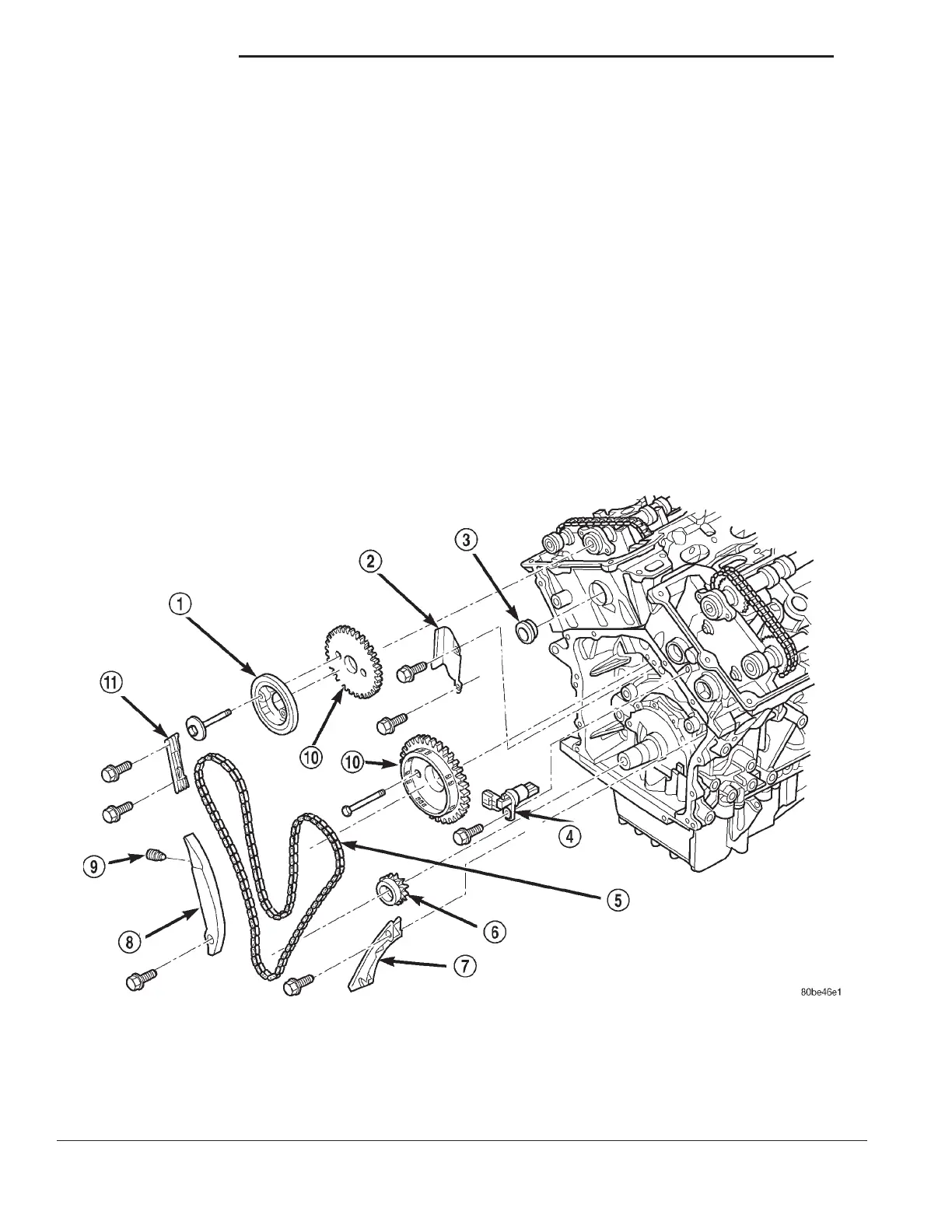
Fig. 69 Primary Timing Drive System
1 – CAMSHAFT DAMPER
2 – CHAIN GUIDE
3 – ACCESS PLUG
4 – CAMSHAFT POSITION SENSOR
5 – PRIMARY TIMING CHAIN
6 – CRANKSHAFT SPROCKET
7 – CHAIN GUIDE
8 – CHAIN TENSIONER ARM
9 – CHAIN TENSIONER
10 – CAMSHAFT SPROCKETS
11 – CHAIN GUIDE
9 - 46 2.7L ENGINE LH
REMOVAL AND INSTALLATION (Continued)