(3) Install the strut assembly to steering knuckle
attaching bolts (Fig. 13). Install nuts on attaching
bolts. Tighten the strut assembly clevis to steering
knuckle attaching bolt nuts to a torque of 203 N·m
(150 ft. lbs.).
(4) Install braking disc back on front hub and
bearing assembly. Install front brake caliper assem-
bly on steering knuckle. Install the 2 caliper assem-
bly to steering knuckle attaching bolts (Fig. 11).
Tighten the caliper assembly guide pin bolts to a
torque of 19 N·m (192 in. lbs.).
(5) If the vehicle is equipped with antilock brakes.
Install the front speed sensor cable routing bracket
onto the front strut assembly (Fig. 10).
(6) Install outer tie rod on strut assembly. Install
tie rod attaching nut. Tighten the tie rod attaching
nut to a torque of 37 N·m (27 ft. lbs.).
(7) Install stabilizer bar link on strut (Fig. 8).
Tighten the stabilizer link attaching nut to a torque
of 95 N·m (70 ft. lbs.).
(8) Install the wheel and tire assembly.
(9) Tighten the wheel mounting nuts in proper
sequence until all nuts are torqued to half specifica-
tion. Then repeat the tightening sequence to the full
specified torque of 129 N·m (95 ft. lbs.).
(10) Lower vehicle.
STEERING KNUCKLE
REMOVE
(1) Raise vehicle on jackstands or centered on a
frame contact type hoist. See Hoisting in the Lubri-
cation and Maintenance section of this manual, for
the required lifting procedure to be used for this
vehicle.
(2) Remove the front wheel and tire assembly from
the vehicle.
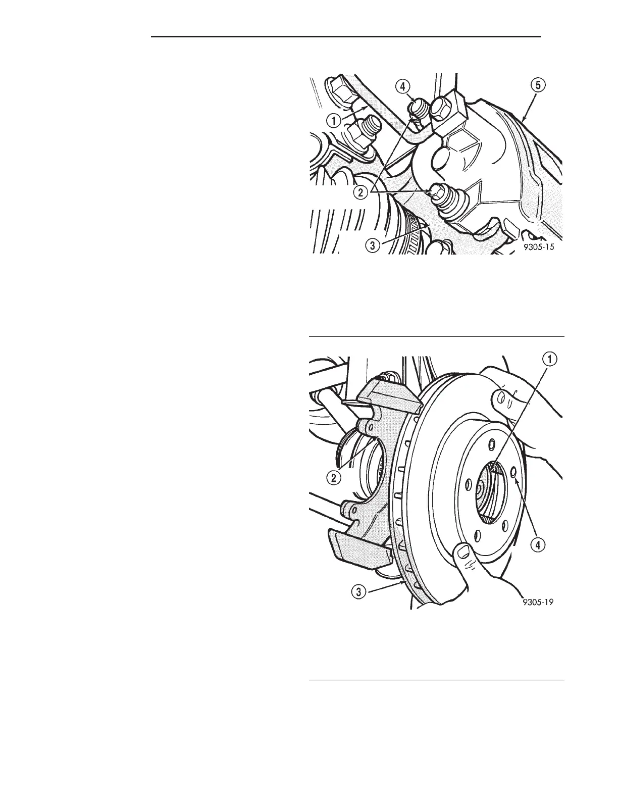
(3) Remove the front caliper assembly from the
front steering knuckle assembly (Fig. 15). Refer to
Front Disc Brake Service in the Brake Section of this
service manual for caliper removal procedure.
(4) Remove front rotor from hub (Fig. 16).
(5) Remove screw attaching wheel speed sensor
head to steering knuckle. Speed sensor head
should be removed from steering knuckle, to
avoid damage to speed sensor by outer C/V
joint when hub and bearing is removed.
(6) Carefully, remove sensor head from steering
knuckle. If the sensor has seized, due to corrosion,
DO NOT USE PLIERS ON SENSOR HEAD. Use
a hammer and punch (Fig. 17) to tap edge of sensor
ear, rocking sensor side to side until free.
(7) Remove the hub and bearing to stub axle
retaining nut (Fig. 18).
(8) Remove the 3 steering knuckle to hub and
bearing assembly attaching bolts (Fig. 19).
Fig. 15 Disc Brake Caliper Mounting
1 – BRAKE LINE
2 – CALIPER GUIDE PIN BOLTS
3 – STEERING KNUCKLE
4 – BLEEDER SCREW
5 – CALIPER ASSEMBLY
Fig. 16 Brake Rotor
1 – HUB
2 – STEERING KNUCKLE
3 – BRAKING DISC (ROTOR)
4 – WHEEL MOUNTING STUD
2 - 18 SUSPENSION LH
REMOVAL AND INSTALLATION (Continued)