with mark on oil pump (Fig. 93). This position will
properly locate oil pump upon installation.
(4) Remove oil pump attaching bolts (Fig. 94).
(5) Remove oil pump.
INSTALLATION
CAUTION: Crankshaft position must be at 60° ATDC
of No.1 cylinder before installing oil pump (Fig. 93).
This position will properly locate oil pump. If not
properly located, severe damage to oil pump can
occur.
(1) Prime oil pump before installation by filling
rotor cavity with engine oil.
(2) If crankshaft has been rotated, it must be repo-
sitioned to 60° ATDC of No.1 cylinder prior to oil
pump installation (Fig. 93).
(3) Install oil pump carefully over crankshaft and
into position.
(4) Install oil pump attaching bolts. Tighten bolts
to 28 N·m (250 in. lbs.) (Fig. 94).
(5) Install oil pick-up tube with new O-ring. Lubri-
cate O-ring before installation. Tighten attaching
bolts to 28 N·m (250 in. lbs.) (Fig. 94).
(6) Install the following remaining components fol-
lowing procedures in this section:
• Oil Pan
• Crankshaft Sprocket
• Timing Chain
• Timing Chain Cover
• Crankshaft Damper
(7) Fill Crankcase with proper engine oil to correct
level.
PISTON AND CONNECTING ROD
REMOVAL
(1) Remove top ridge of cylinder bores with a reli-
able ridge reamer before removing pistons from cyl-
inder block. Be sure to keep tops of pistons
covered during this operation. Pistons and con-
necting rods must be removed from top of cyl-
inder block. When removing piston and
connecting rod assemblies from the engine,
rotate crankshaft so that each connecting rod
is centered in cylinder bore.
NOTE: Connecting rod bearing caps are not inter-
changeable and should be marked before removing
to ensure correct reassembly.
CAUTION: DO NOT use a number stamp or a punch
to mark connecting rods. Damage to connecting
rod could occur.
(2) Mark connecting rod and bearing cap positions
using a permanent ink marker or scribe tool (Fig.
95).
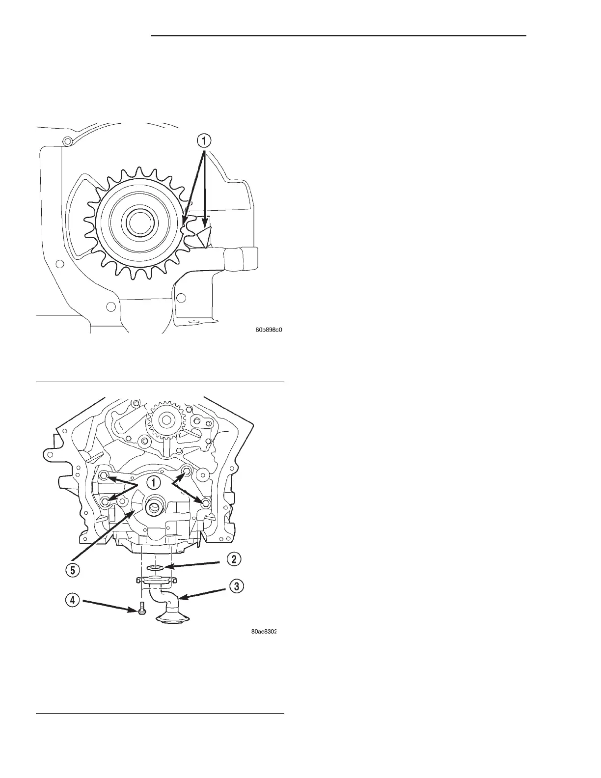
Fig. 93 Crankshaft Positioned At 60° ATDC No.1
Cylinder
1 – CRANKSHAFT POSITION = 60° ATDC NO. 1 CYLINDER
Fig. 94 Oil Pump and Pick-up Tube
1 – BOLTS
2 – O-RING
3 – PICK-UP TUBE
4 – BOLT
5 – OIL PUMP
9 - 58 2.7L ENGINE LH
REMOVAL AND INSTALLATION (Continued)