DIAGNOSIS AND TESTING
AUTOMATIC DAY/NIGHT INSIDE MIRROR
Operational test:
• Turn ignition switch to the ON position with the
vehicle in park.
• Place mirror switch in the high position.
• Cover the forward facing sensor with dark cloth
to keep out any ambient light.
• Shine a light into the rear facing sensor, watch
to see if the mirror darkens.
With the mirror darkened, place the vehicle in
reverse, the mirror should return to its normal con-
dition.
If the above conditions are met the mirror is oper-
ating properly. If not OK, test voltage.
Test three way connector harness.
(1) Pin 1 Ignition Switch in run position, should
have battery voltage.
(2) Pin 2 Should have continuity to Ground.
(3) Pin 3 Senses when the transmission is in
reverse. There should be battery voltage present
when transmission is in the reverse position.
(4) If test is OK replace Mirror.
(5) If not refer, to Group 8W, Wiring Diagrams
manual to test the circuits.
HEATED MIRROR
(1) Check fuse 1 in the Junction Block and repair
as necessary.
(2) Using a ohmmeter, check Pin 1 of the mirror
motor harness connector for continuity to ground. If
OK, go to Step 3. If not OK, repair as necessary.
Refer to Group 8W, Wiring Diagrams for proper Pin
location.
(3) Activate the rear window defogger switch, use
a voltmeter and check Pin 3 for battery voltage.
(a) If OK, go to Step 4. If not OK, Step b
(b) Check rear window defogger switch, refer to
Group 8N, Electrically Heated Systems. If OK, go
to Step c. If not OK, repair as necessary.
(c) If no voltage repair wire as necessary. Refer
to Group 8W, Wiring Diagrams.
(4) Remove mirror glass and check wires. If wires
are OK, replace mirror glass. If not OK, repair as
necessary or replace mirror.
MIRROR MOTOR
(1) Using a trim stick, remove power mirror switch
from mounting position.
(2) Disconnect wire harness connector.
(3) Using two jumper wires, one connected to a 12
volt source, and the other connected to a good body
ground. Jumpers are applied to the mating switch
connector on the wire harness. Refer to the Mirror
Test table and (Fig. 2) for appropriate mirror
response.
(4) If test results are not obtained as shown in the
(Fig. 2), check for open or shorted circuit, or replace
mirror assembly as necessary.
MIRROR SWITCH
(1) Remove trim panel. Refer to Group 23, Body
for Removal and Installation procedures.
(2) Disconnect wire harness connector from back of
power mirror switch.
(3) Disengage lock tabs at both ends of switch and
remove power mirror switch from door trim panel.
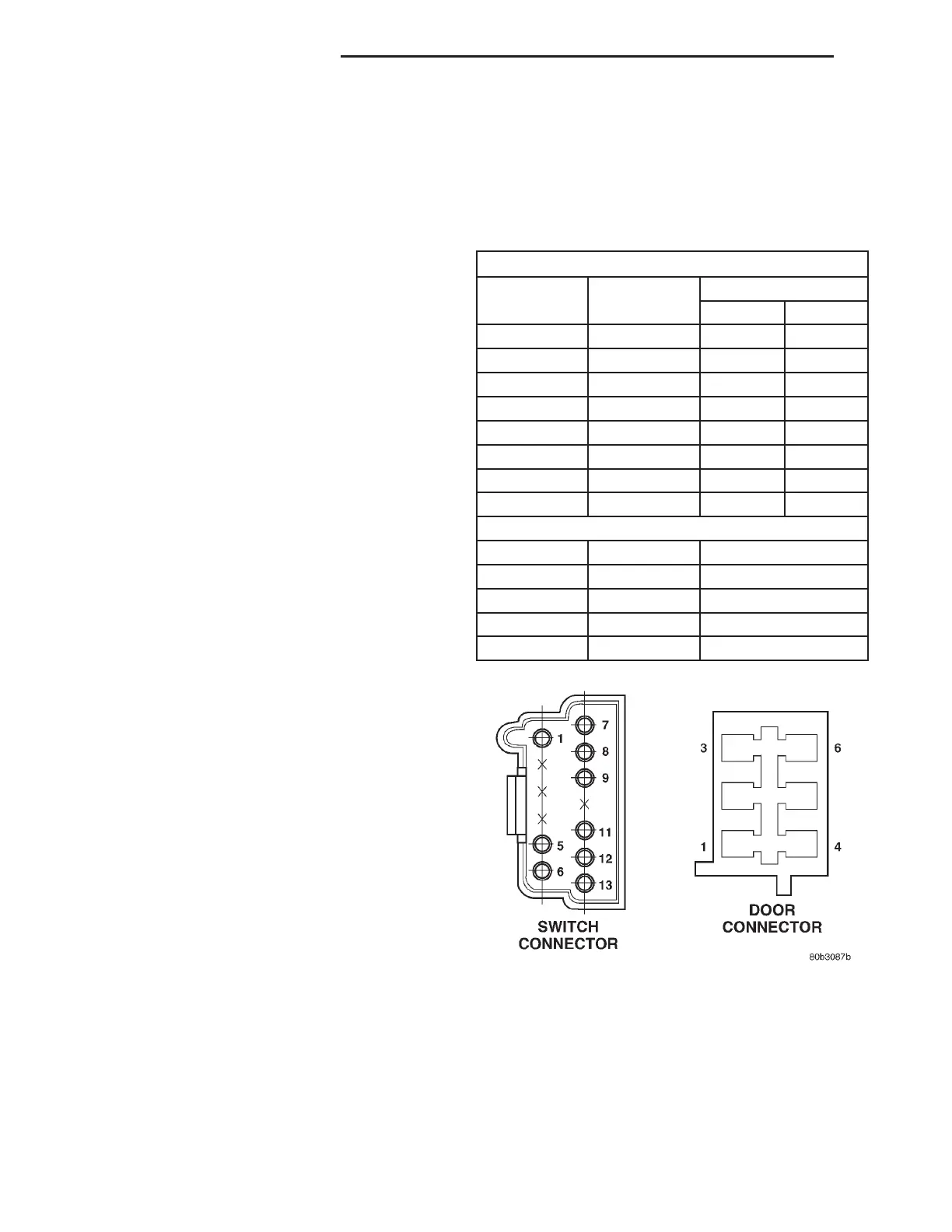
MIRROR TEST
MIRROR SWITCH CONNECTOR
B (+) B (-) MIRROR REACTION
LEFT RIGHT
PIN 12 PIN 6 UP
PIN 13 PIN 1 UP
PIN 6 PIN 12 DOWN
PIN 1 PIN 13 DOWN
PIN 6 PIN 7 RIGHT
PIN 1 PIN 8 RIGHT
PIN 7 PIN 6 LEFT
PIN 8 PIN 1 LEFT
DOOR CONNECTOR
PIN 6 PIN 2 UP
PIN 2 PIN 6 DOWN
PIN 2 PIN 5 RIGHT
PIN 5 PIN 2 LEFT
PIN 1 PIN 3 HEATER
Fig. 2 Connector Pin Call-Out
8T - 2 POWER MIRROR SYSTEMS LH