ABS GENERAL DIAGNOSTICS INFORMATION
This section contains information necessary to
diagnose the antilock brake system. Specifically, this
section should be used to help diagnose conditions
which result in any of the following:
(1) amber ABS warning lamp turned on.
(2) brakes lock-up on hard application.
Diagnosis of base brake conditions that are obvi-
ously mechanical in nature should be directed to
BASE BRAKE SYSTEM at the beginning of this
group.
Many ABS conditions judged to be a problem by
the driver may be normal operating conditions. See
ABS OPERATION in the DESCRIPTION AND
OPERATION section of this group to become famil-
iarized with the normal characteristics of this
antilock brake system.
ABS WIRING DIAGRAM INFORMATION
During the diagnosis and testing of the antilock
brake system it may become necessary to reference
the wiring diagrams covering the antilock brake sys-
tem and its components. For wiring diagrams refer to
GROUP 8W of this service manual. It will provide
you with the wiring diagrams and the circuit descrip-
tion and operation information covering the antilock
brake system.
ABS VEHICLE TEST DRIVE
Most ABS complaints will require a test drive to
properly duplicate and diagnose the condition.
WARNING: CONDITIONS THAT RESULT IN TURN-
ING ON THE RED BRAKE WARNING LAMP MAY
INDICATE REDUCED BRAKING ABILITY.
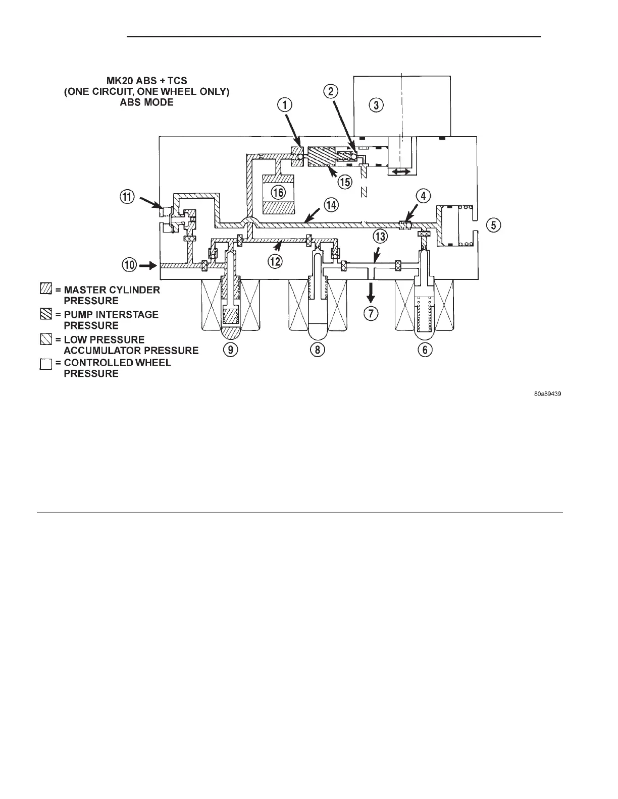
Fig. 9 ABS With Traction Control - ABS Mode Hydraulic Circuit
1 – OUTLET VALVE
2 – PUMP PISTON
3 – PUMP MOTOR (ON)
4 – SUCTION VALVE
5 – LOW PRESSURE ACCUMULATOR
6 – NORMALLY CLOSED VALVE (MODULATING)
7 – TO RIGHT FRONT WHEEL
8 – NORMALLY OPEN VALVE (MODULATING)
9 – NORMALLY OPEN ASR VALVE (OFF)
10 – FROM MASTER CYLINDER
11 – HYDRAULIC SHUTTLE VALVE
12 – MASTER CYLINDER PRESSURE
13 – CONTROLLED WHEEL PRESSURE
14 – LOW PRESSURE ACCUMULATOR PRESSURE
15 – PUMP INTERSTAGE PRESSURE
16 – NOISE DAMPER CHAMBER
5 - 64 BRAKES LH
DIAGNOSIS AND TESTING (Continued)

 Loading...


