(3) Align crankshaft sprocket timing mark to mark
on oil pump housing (Fig. 70). The mark on oil pump
housing is 60° ATDC of #1 cylinder.
CAUTION: When the timing chain is removed and
the cylinder heads are still installed, DO NOT rotate
the camshafts or crankshaft without first locating
the proper crankshaft position. Failure to do so will
result in valve and/or piston damage.
(4) Remove primary timing chain tensioner from
right cylinder head (Fig. 74).
(5) Remove camshaft position sensor from left cyl-
inder head (Fig. 69).
(6) Remove chain guide access plug from left cylin-
der head (Fig. 69).
NOTE: When camshaft sprocket bolts are removed,
the camshafts will rotate in a clockwise direction.
(7) Starting with the right camshaft sprocket,
remove the sprocket attaching bolts. Remove cam-
shaft damper and sprocket (Fig. 69).
(8) Remove left side camshaft sprocket attaching
bolts and remove sprocket (Fig. 69).
(9) Remove lower chain guide and tensioner arm
(Fig. 69).
(10) Remove the primary timing chain.
INSTALLATION
(1) Inspect all sprockets and chain guides. Replace
if worn. Refer to crankshaft sprocket, for removal
and installation procedures in this section.
(2) If removed, install right and left side short
chain guides (Fig. 69). Tighten attaching bolts to 28
N·m (250 in. lbs.).
(3) Align crankshaft sprocket timing mark to the
mark on oil pump housing (Fig. 71).
NOTE: Lubricate timing chain and guides with
engine oil before installation.
(4) Place left side primary chain sprocket onto the
chain so that the timing mark is located in-between
the two (plated) timing links (Fig. 71).
(5) Lower the primary chain with left side sprocket
through the left cylinder head opening.
NOTE: The camshaft sprockets can be allowed to
float on the camshaft hub during installation.
(6) Loosely position left side camshaft sprocket
over camshaft hub.
(7) Align timing (plated) link to the crankshaft
sprocket timing mark (Fig. 71).
(8) Position primary chain onto water pump drive
sprocket.
(9) Align right camshaft sprocket timing mark to
the timing (plated) link on the timing chain (Fig. 71)
and loosely position over camshaft hub.
(10) Verify that all chain timing (plated) links are
properly aligned to the timing marks on all sprockets
(Fig. 71).
(11) Install left side lower chain guide and ten-
sioner arm (Fig. 69). Tighten attaching bolts to 28
N·m (250 in. lbs.).
NOTE: Inspect oil ring on chain guide access plug
before installing. Replace O-ring as necessary.
(12) Install chain guide access plug to left side cyl-
inder head (Fig. 69). Tighten plug to 20 N·m (15 ft.
lbs.).
NOTE: To reset the primary timing chain tensioner,
engine oil will first need to be purged from the ten-
sioner (Fig. 72).
(13) Purge oil from timing chain tensioner using
the following procedure:
(a) Place the check ball end of tensioner into the
shallow end of Special Tool 8186 (Fig. 72).
(b) Using hand pressure, slowly depress ten-
sioner until oil is purged from tensioner (Fig. 72).
(14) Reset timing chain tensioner using the follow-
ing procedure:
(a) Position cylinder plunger into the deeper end
of Special Tool 8186 (Fig. 73).
(b) Apply a downward force until tensioner is
reset (Fig. 73).
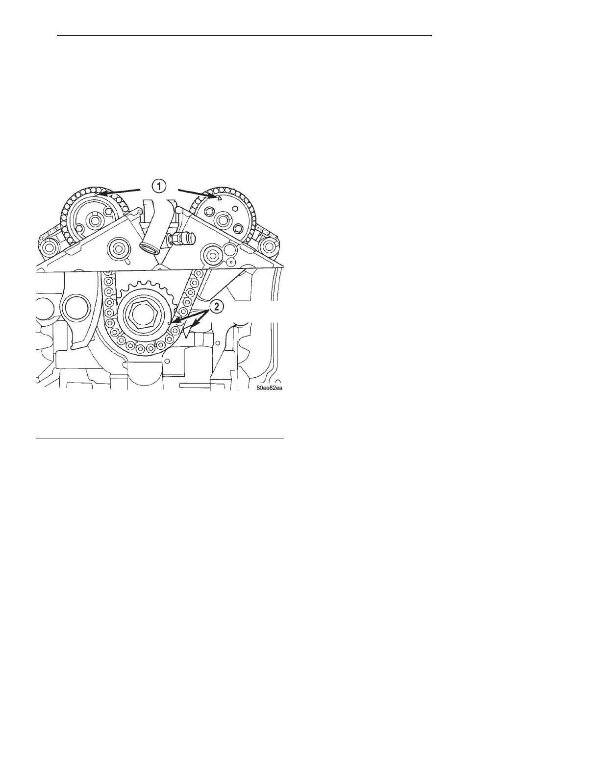
Fig. 70 Timing Mark Alignment
1 – CAMSHAFT TIMING MARKS
2 – CRANKSHAFT TIMING MARKS
LH 2.7L ENGINE 9 - 47
REMOVAL AND INSTALLATION (Continued)