OPERATION
The CMP sensor contains a hall effect device called
a sync signal generator to generate a fuel sync sig-
nal. The camshaft position sensor helps provide cyl-
inder identification to the Powertrain Control Module
(PCM) (Fig. 10) or (Fig. 11). The sensor generates
pulses as groups of notches on the camshaft sprocket
pass underneath it. The PCM keeps track of crank-
shaft rotation and identifies each cylinder by the
pulses generated by the notches on the camshaft
sprocket. Crankshaft pulses follow each group of
camshaft pulses.
When metal aligns with the sensor, voltage goes
low (less than 0.3 volts). When a notch aligns with
the sensor, voltage spikes high (5.0 volts). As a group
of notches pass under the sensor, the voltage
switches from low (metal) to high (notch) then back
to low. The number of notches determine the amount
of pulses. If available, an oscilloscope can display the
square wave patterns of each timing event.
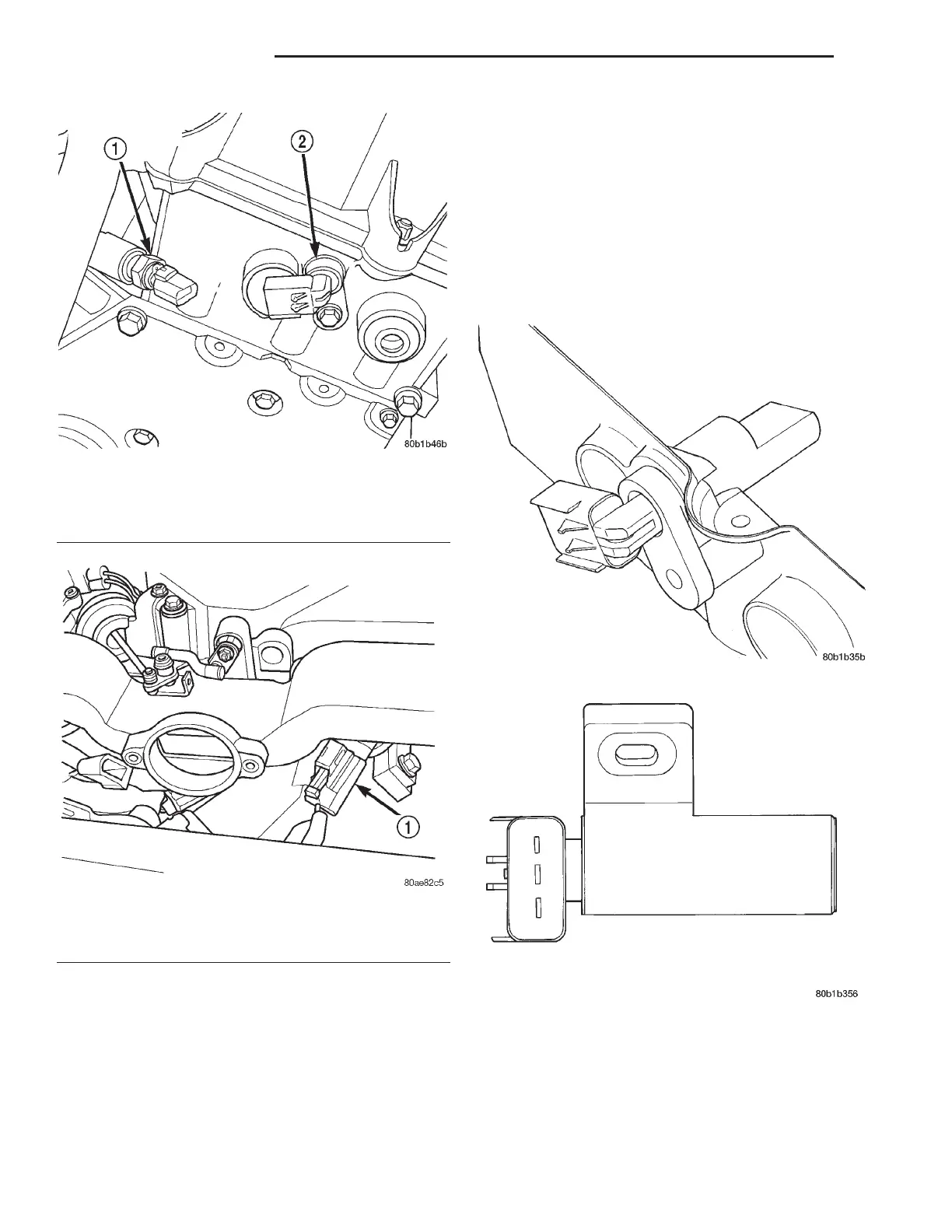
Fig. 8 Camshaft Position Sensor Location—2.7L
Engine
1 – ENGINE COOLANT TEMPERATURE SENSOR
2 – CAM SENSOR
Fig. 9 Camshaft Position Sensor Location—3.2/3.5L
Engine
1 – CAMSHAFT SENSOR
Fig. 10 Camshaft Position Sensor—2.7L Engine
Fig. 11 Camshaft Position Sensor—3.2/3.5L Engine
8D - 4 IGNITION SYSTEM LH
DESCRIPTION AND OPERATION (Continued)