common electric motor (Fig. 3). This DC-type motor
is integral to the HCU and is controlled by the CAB.
The pump/motor provides the extra amount of
brake fluid needed during antilock braking. Brake
fluid is released to the accumulators when the outlet
valve is opened during an antilock stop. The pump
mechanism consists of two opposing pistons operated
by an eccentric camshaft. In operation, one piston
draws fluid from the accumulators, and the opposing
piston pumps fluid to the master cylinder circuits.
When the antilock stop is complete, the pump/motor
drains the accumulators.
The CAB may turn on the pump/motor when an
antilock stop is detected. The pump/motor continues
to run during the antilock stop and is turned off after
the stop is complete. Under some conditions, the
pump/motor runs to drain the accumulators during
the next drive-off.
The pump/motor is not a serviceable item; if it
requires replacement, the HCU must be replaced.
ABS FUSES
DESCRIPTION
The ABS fuses and the ABS pump/motor fuse are
located in the power distribution center (PDC). Refer
to the label on the inside of the PDC cover for the
location of these fuses. The PDC is located on the
driver’s side of the engine compartment in front of
the strut tower.
ABS RELAYS (SOLID STATE)
DESCRIPTION
Two internal relays are used to control the antilock
brake system. The two relays are the pump/motor
relay and the system relay. The pump/motor relay
and the system relay are located in the CAB. If
either the pump/motor relay or the system relay is
diagnosed as not functioning properly, the CAB must
be replaced. Refer to INTEGRATED CONTROL
UNIT in the DISASSEMBLY AND ASSEMBLY sec-
tion in this section of this service manual group for
the procedure to remove the CAB from the HCU.
AMBER ABS WARNING LAMP
DESCRIPTION
The amber ABS warning lamp is located on the left
side of the instrument panel in the instrument clus-
ter. The purpose of the warning lamp is discussed in
detail below.
OPERATION
When the ignition key is turned to the ON posi-
tion, the amber ABS warning lamp is lit until the
CAB completes it’s self-tests and turns off the lamp
(approximately 4 seconds). The amber ABS warning
lamp will illuminate when the CAB detects a condi-
tion that results in the shutdown of ABS function or
when the instrument cluster does not receive mes-
sages from the CAB. The CAB sends a message
across the PCI BUS circuit that informs the instru-
ment cluster to turn on the amber ABS warning
lamp.
NOTE: If the vehicle is equipped with traction con-
trol, the TRAC OFF lamp will illuminate anytime the
amber ABS warning lamp illuminates.
Under most conditions, when the amber ABS warn-
ing lamp is on, only the ABS function of the brake
system is affected; the base brake system and the
ability to stop the vehicle are not affected.
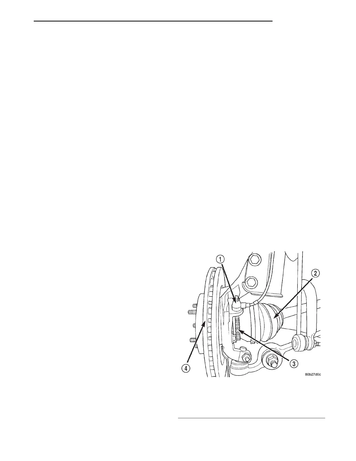
WHEEL SPEED SENSOR (WSS) AND TONE WHEEL
DESCRIPTION
One wheel speed sensor (WSS) and one tone wheel
are located at each front and rear wheel. Each front
wheel speed sensor is attached to a boss in the steer-
ing knuckle (Fig. 4). The front tone wheel is part of
the outboard constant velocity joint. The rear wheel
speed sensor on rear disc brake applications is
mounted to the rear disc brake adapter (Fig. 5). The
rear tone wheel is an integral part of the rear wheel
hub and bearing.
Fig. 4 Front Wheel Speed Sensor
1 – WHEEL SPEED SENSOR
2 – CV BOOT
3 – TONE WHEEL
4 – ROTOR
LH BRAKES 5 - 59
DESCRIPTION AND OPERATION (Continued)