CAUTION: The collar must be tighten using the fol-
lowing procedure, as damage to the collar or oil
pan may occur.
(7) Install structural collar (Fig. 85) using the fol-
lowing tightening sequence:
(a) Install the vertical collar to oil pan bolts.
Torque bolts initially to 1.1 N·m (10 in. lbs.).
(b) Install the horizontal collar to transmission
bolts and torque to 55 N·m (40 ft. lbs.).
(c) Starting with the center vertical bolts and
working outward, final torque bolts to 55 N·m (40
ft. lbs.).
(8) Install oil filter and drain plug.
(9) Connect suspension stabilizer bar. Refer to
SUSPENSION for procedure.
(10) Lower vehicle and install oil dipstick and
tube.
(11) Fill engine crankcase with proper oil to cor-
rect level.
CRANKSHAFT
REMOVAL
(1) Remove engine from vehicle. Refer to procedure
in this section.
(2) Mount engine on an engine stand.
(3) Drain engine oil and remove oil filter.
(4) Remove oil pan and oil pick-up tube.
(5) Remove idler pulley bracket for accessory drive
belt.
(6) Remove upper intake manifold. Refer to proce-
dure in this section.
(7) Remove cylinder head covers.
(8) Remove timing chain cover.
(9) Remove primary timing chain.
(10) Remove crankshaft sprocket.
(11) Remove oil pump.
(12) Remove crankshaft rear oil seal retainer.
(13) Remove structural windage tray (Fig. 91).
(14) Turn crankshaft until connecting rod cap to be
removed is accessible.
NOTE: Connecting rod bearing caps are not inter-
changeable and should be marked before removing
to ensure correct reassembly.
CAUTION: DO NOT use a number stamp or a punch
to mark connecting rods. Damage to connecting
rod could occur.
(15) Mark connecting rod bearing cap positions
using a permanent ink marker or scribe tool.
(16) Remove connecting rod bearing caps. Use care
to prevent damage to the crankshaft bearing sur-
faces.
CAUTION: Care should be taken not to damage the
fractured rod and cap joint face surfaces or damage
to the engine may occur.
(17) Remove main bearing cap bolts and tie bolts
(Fig. 87).
(18) Remove main bearing caps (Fig. 87).
CAUTION: When removing crankshaft, use care not
to damage bearing surfaces on the crankshaft.
(19) Remove crankshaft from cylinder block.
INSTALLATION
NOTE: Upper and lower bearing halves are NOT
interchangeable.
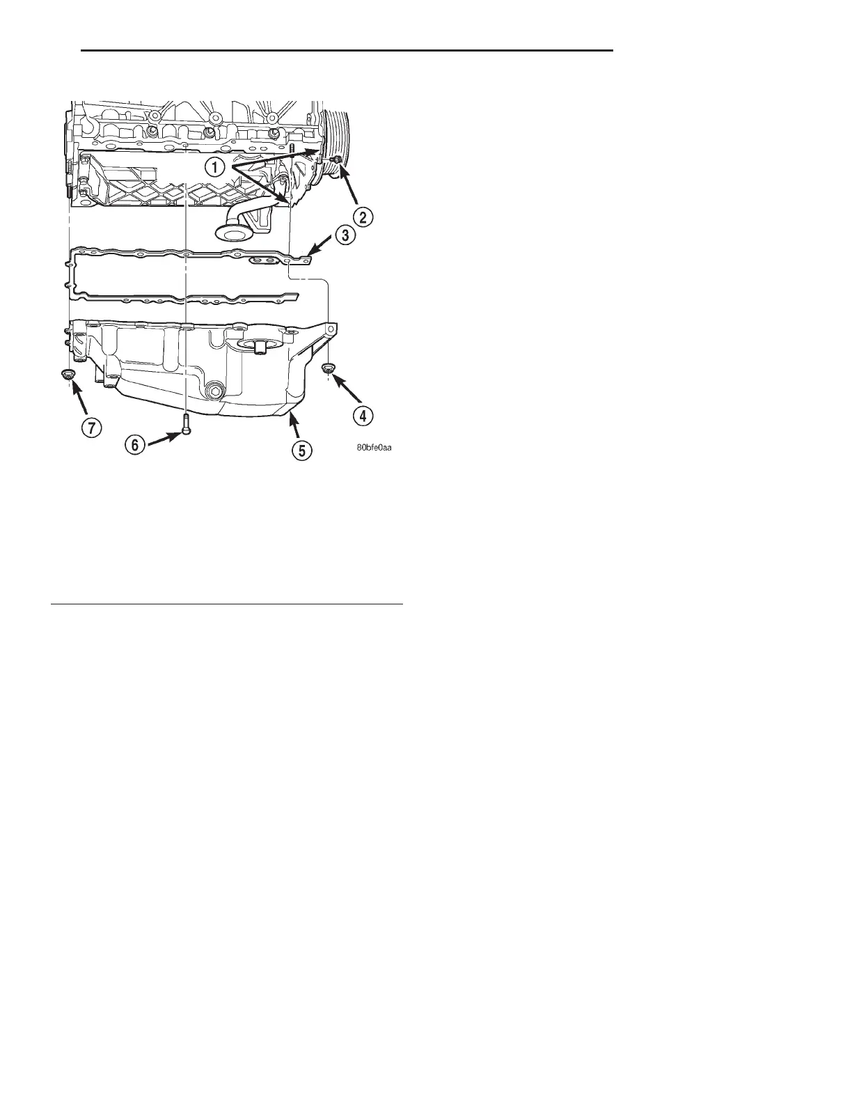
Fig. 86 Oil Pan
1 – SEALER LOCATION
2 – BOLT-M6
3 – GASKET
4 – NUT-M6
5 – OIL PAN
6 – BOLT-M8
7 – NUT-M6
LH 2.7L ENGINE 9 - 55
REMOVAL AND INSTALLATION (Continued)