(1) To disable the Ignition and Fuel systems, dis-
connect the Automatic Shutdown Relay (ASD). The
ASD relay is located in the Power Distribution Cen-
ter (PDC). Refer to the PDC cover for proper relay
location.
(2) Remove the air cleaner assembly for access to
battery terminals. Refer to Group 14, Fuel for service
procedures.
(3) With all wiring harnesses and components
properly connected, perform the following:
(a) Connect the negative lead of the voltmeter to
the battery negative post, and positive lead to the
battery negative cable clamp. Rotate and hold the
ignition switch in the START position. Observe the
voltmeter. If voltage is detected, correct poor con-
tact between cable clamp and post.
(b) Connect positive lead of the voltmeter to the
battery positive post, and negative lead to the bat-
tery positive cable clamp. Rotate and hold the igni-
tion switch key in the START position. Observe the
voltmeter. If voltage is detected, correct poor con-
tact between the cable clamp and post.
(c) Connect negative lead of voltmeter to battery
negative terminal, and positive lead to engine
block near the battery cable attaching point.
Rotate and hold the ignition switch in the START
position. If voltage reads above 0.2 volt, correct
poor contact at ground cable attaching point. If
voltage reading is still above 0.2 volt after correct-
ing poor contacts, replace ground cable.
(4) Connect positive voltmeter lead to the starter
motor housing and the negative lead to the battery
negative terminal. Hold the ignition switch key in
the START position. If voltage reads above 0.2 volt,
correct poor starter to engine ground.
(a) Connect the positive voltmeter lead to the
battery positive terminal, and negative lead to bat-
tery cable terminal on starter solenoid. Rotate and
hold the ignition switch in the START position. If
voltage reads above 0.2 volt, correct poor contact at
battery cable to solenoid connection. If reading is
still above 0.2 volt after correcting poor contacts,
replace battery positive cable.
(b) If resistance tests do not detect feed circuit
failures, replace the starter motor.
FEED CIRCUIT TEST
NOTE: The following results are based upon the
vehicle being at room temperature.
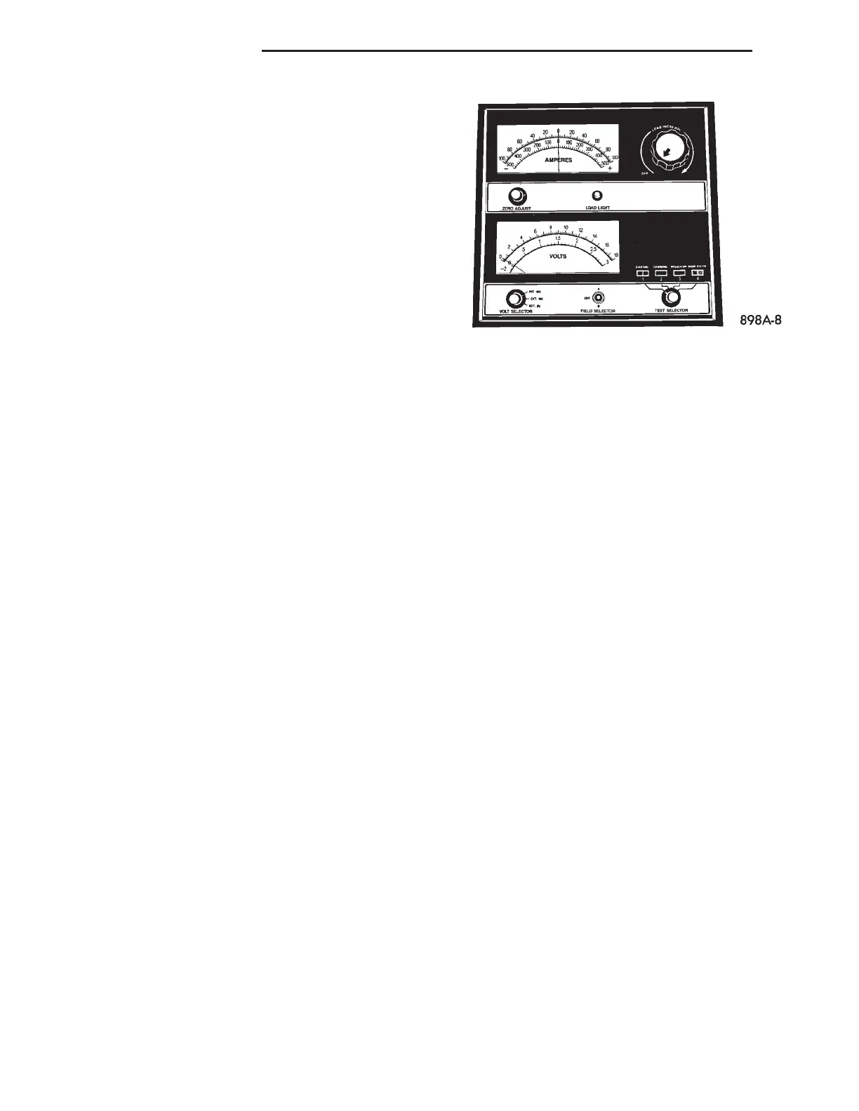
The following procedure will require a suitable
volt-ampere tester (Fig. 2).
CAUTION: Before performing any starter tests, the
ignition and fuel systems must be disabled.
(1) Connect a volt-ampere tester to the battery ter-
minals. Refer to the operating instructions provided
with the tester being used.
(2) To disable the ignition and fuel systems, dis-
connect the Automatic Shutdown Relay (ASD). The
ASD relay is located in the Power Distribution Cen-
ter (PDC). Refer to the PDC cover for proper relay
location.
(3) Verify that all lights and accessories are OFF,
and the transmission shift selector is in the PARK
and SET parking brake.
CAUTION: Do not overheat the starter motor or
draw the battery voltage below 9.6 volts during
cranking operations.
(4) Rotate and hold the ignition switch in the
START position. Observe the volt-ampere tester (Fig.
2).
• If voltage reads above 9.6 volts, and amperage
draw reads above 280 amps, check for engine seizing
or faulty starter.
• If voltage reads 12.4 volts or greater and amper-
age reads 0 to 10 amps, check for corroded cables
and/or bad connections.
• Voltage below 9.6 volts and amperage draw
above 300 amps, the problem is the starter. Replace
the starter refer to starter removal.
(5) After the starting system problems have been
corrected, verify the battery state-of-charge and
charge battery if necessary. Disconnect all testing
equipment and connect ASD relay. Start the vehicle
several times to assure the problem has been cor-
rected.
STARTING SYSTEM TEST
For circuit descriptions and diagrams, refer to
Group 8W, Wiring Diagrams.
Fig. 2 Volt Ampere Tester
8B - 4 STARTING SYSTEMS LH
DIAGNOSIS AND TESTING (Continued)