INSTALLATION
(1) Install the nut, washers, and rubber isolators
securing the stabilizer bar attaching link to the strut.
(2) Position the strut assembly back in the vehicle
with the 3 studs on the strut mount through the
holes in the strut tower. Install the 3 strut mount to
body attaching nuts onto mounting studs (Fig. 11).
Tighten the 3 strut mount attaching nuts to a torque
of 25 N·m (19 ft. lbs.).
(3) Raise vehicle back up to working height for
reconnecting lower strut.
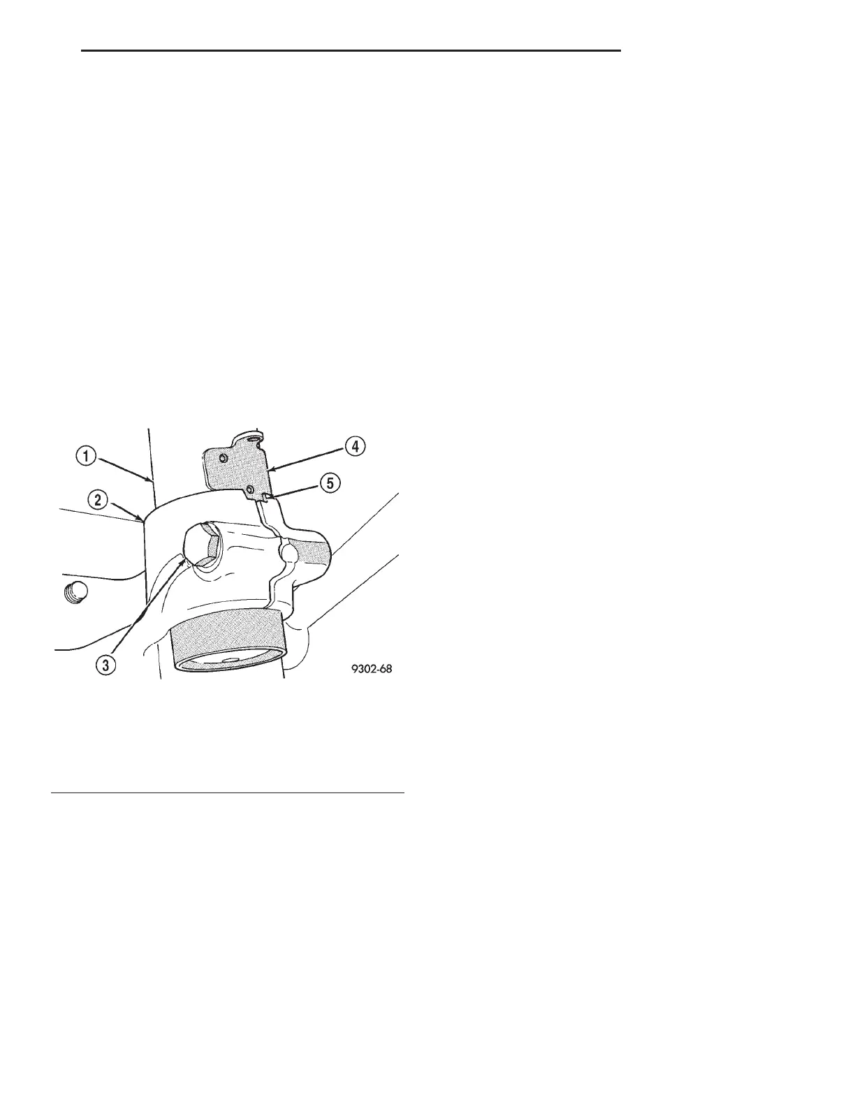
(4) Install spindle onto bottom of the strut assem-
bly. Push or tap spindle assembly onto lower end of
strut, until notch in spindle is tightly seated against
locating tab on strut assembly (Fig. 12). Then remove
center punch from hole in spindle. Install spindle to
strut assembly pinch bolt into spindle (Fig. 12).
Tighten spindle to strut assembly pinch bolt to 53
N·m (40 ft. lbs.).
(5) Install the lateral links on the spindle (Fig. 6).
Install, but DO NOT fully tighten lateral links to
spindle attaching bolt at this time.
CAUTION: Tightening lateral link attaching bolt to
spindle at this time will contort the bushing at curb
height and lead to bushing failure. This bolt is to be
tightened only when the vehicle is at curb riding
height.
(6) Install stabilizer bar attaching link onto stabi-
lizer bar (Fig. 7). Install stabilizer link to stabilizer
bar attaching nut (Fig. 7). Tighten the stabilizer link
to stabilizer bar attaching nut to a torque of 95 N·m
(70 ft. lbs.) using a crow foot wrench and torque
wrench in place of the wrench on the attaching nut.
Be sure to use a wrench to hold the link stud in
place while tightening attaching nut.
(7) Install rear wheel speed sensor into brake cal-
iper adapter. Install head attaching bolt (Fig. 5) and
tighten to 7 N·m (60 in. lbs.).
(8) Install rear braking disc on hub. Carefully
install rear brake caliper over braking disc and
install on adapter. Tighten rear caliper assembly to
adapter mounting bolts to 22 N·m (192 in. lbs.).
(9) Install wheel and tire assembly on vehicle.
Then torque all wheel mounting stud nuts in proper
sequence until all nuts are torqued to half specifica-
tion. Then repeat tightening sequence to full speci-
fied torque of 129 N·m (95 ft. lbs.).
(10) Lower vehicle to the ground.
(11) With the weight of the vehicle on the tires,
tighten lateral link to spindle attaching bolt to 135
N·m (100 ft. lbs.).
(12) Reconnect the radio speaker wiring to the
rear speaker. Install rear radio speaker and mount-
ing bracket using 4 screws.
(13) Install both lower quarter and upper quarter
trim panels Refer to Body Components in the Body
section of this manual for the required procedure to
be used for this vehicle.
(14) Install the rear seat back, and seat cushion.
Refer to Seats in the Body section of this manual for
the required procedure to be used for this vehicle.
(15) Check and reset rear wheel TOE to specifica-
tions if required.
SPINDLE
REMOVAL
(1) Raise vehicle on jackstands or centered on a
frame contact type hoist. See Hoisting in the Lubri-
cation and Maintenance section of this manual, for
the required lifting procedure to be used for this
vehicle.
(2) Remove the rear wheel and tire assembly from
the vehicle.
(3) Remove the rear caliper assembly from the
adapter. Refer to Rear Disc Brakes in Group 5
Brakes of this Service manual for required caliper
removal procedure. After removing caliper assembly
store caliper by hanging it from frame of vehicle (Fig.
13). Do not let weight of rear caliper assembly hang
from flexible brake hose. If vehicle is equipped with
rear drum brakes, remove the brake flex hose
bracket from the support plate and wheel cylinder.
(4) Remove rear braking disc from hub.
(5) Remove rear hub and bearing assembly cotter
pin and nut retainer (Fig. 14). Remove the hub and
bearing retaining nut and washer from the spindle
Fig. 12 Spindle Attachment To Strut
1 – STRUT ASSEMBLY
2 – SPINDLE
3 – PINCH BOLT
4 – LOCATING TAB
5 – NOTCH
LH SUSPENSION 2 - 51
REMOVAL AND INSTALLATION (Continued)