OPERATION
The injector contains a pintle that closes off an ori-
fice at the nozzle end. When electric current is sup-
plied to the injector, the armature and needle move a
short distance against a spring, allowing fuel to flow
out the orifice. Because the fuel is under high pres-
sure, a fine spray is developed in the shape of 2
streams. The spraying action atomizes the fuel, add-
ing it to the air entering the combustion chamber.
The PCM provides battery voltage to each injector
through the ASD relay. Injector operation is con-
trolled by a ground path provided for each injector by
the PCM. Injector on-time (pulse-width) is variable,
and is determined by the PCM processing all the
data previously discussed to obtain the optimum
injector pulse width for each operating condition. The
pulse width is controlled by the duration of the
ground path provided.
Fuel injectors are fired one crankshaft revolution
before TDC compression. When cylinder #4 is at TDC
compression the injector for cylinder #1 will be ener-
gized.
FUEL FILTER/FUEL PRESSURE REGULATOR
DESCRIPTION
A combination fuel filter and fuel pressure regula-
tor is used on all gas powered engines. It is located
on the top of the fuel pump module.
It contains a diaphragm, calibrated springs and a
fuel return valve. The internal fuel filter (Fig. 4) is
also part of the assembly.
OPERATION
Fuel Pressure Regulator Operation: The pres-
sure regulator is a mechanical device that is cali-
brated to maintain fuel system operating pressure of
approximately 400 kPa (58 psi) at the fuel injectors.
Fuel is supplied to the filter/regulator by the elec-
tric fuel pump through an opening tube at the bot-
tom of filter/regulator.
The fuel pump module contains a check valve to
maintain some fuel pressure when the engine is not
operating. This will help to start the engine.
If fuel pressure at the pressure regulator exceeds
approximately 58 psi, an internal diaphragm closes
and excess fuel pressure is routed back into the tank
through the pressure regulator. A separate fuel
return line is not used with any gas powered engine.
PRESSURE-VACUUM FILLER CAP
DESCRIPTION
The plastic fuel fill cap is threaded/quarter turn
onto the end of the fuel filler tube. It’s purpose is to
retain vapors and fuel in the fuel tank.
OPERATION
The fuel filler cap incorporates a two-way relief
valve that is closed to atmosphere during normal
operating conditions. The relief valve is calibrated to
open when a pressure of 17 kPa (2.5 psi) or vacuum
of 2 kPa (0.6 in. Hg) occurs in the fuel tank. When
the pressure or vacuum is relieved, the valve returns
to the normally closed position.
CAUTION: Remove the fuel filler cap to release fuel
tank pressure before disconnecting any fuel system
component.
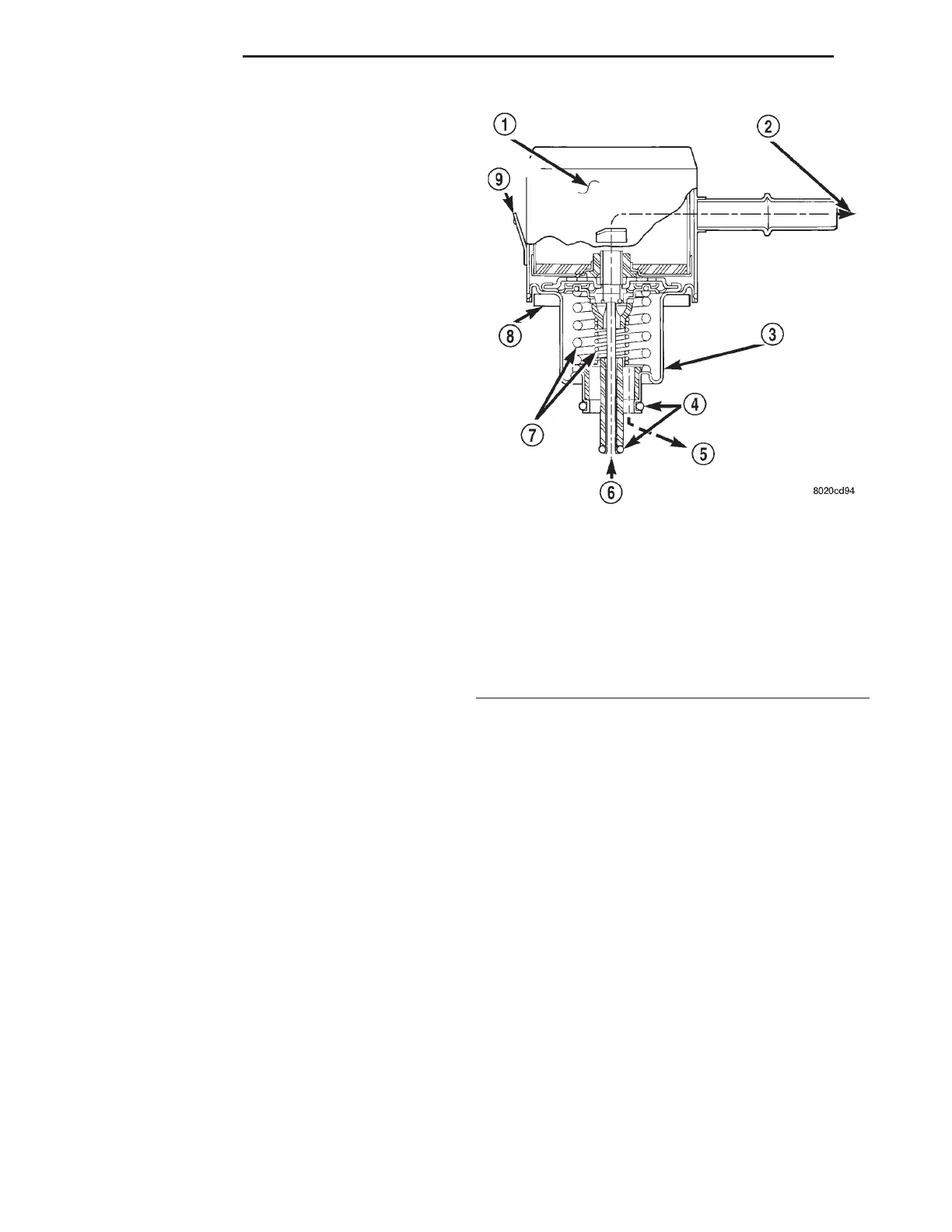
Fig. 4 Side View—Filter/Regulator
1 – INTERNAL FUEL FILTER
2 – FUEL FLOW TO FUEL INJECTORS
3 – FUEL FILTER/FUEL PRESSURE REGULATOR
4 – O-RINGS
5 – EXCESS FUEL BACK TO TANK
6 – FUEL INLET
7 – CALIBRATED SPRINGS
8 – RUBBER GROMMET AT PUMP MODULE
9 – LOCKING TAB
14 - 4 FUEL SYSTEM LH
DESCRIPTION AND OPERATION (Continued)