INSTALL
CAUTION: If the master cylinder is being replaced
or or has been repaired, the master cylinder must
be bled before installation. See Master Cylinder
Bleeding in Service Procedures within this group of
this service manual.
(1) Install master cylinder on studs of vacuum
booster, aligning the vacuum booster push rod with
master cylinder piston.
(2) Install the master cylinder mounting nuts (Fig.
40). Tighten the nuts to a torque of 28 N·m (250 in.
lbs.).
(3) Connect brake tubes to master cylinder pri-
mary and secondary ports. Tighten fittings to 17 N·m
(145 in. lbs.) torque.
(4) Reconnect brake fluid level sensor.
POWER BRAKE BOOSTER
REMOVAL
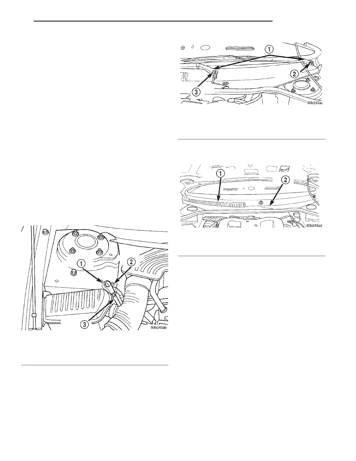
(1) Remove the battery ground cable from the
ground stud on the right strut tower. Then, correctly
isolate the ground cable by installing the cable isola-
tor on the ground stud (Fig. 41).
(2) Remove caps from both wiper arms at the
attachment to the pivots to expose the wiper arm
attaching nut. Remove the nut (Fig. 42) attaching
each wiper arm to its pivot.
(3) Remove the wiper arms from the pivots. Wiper
arms are removed from the pivots by rocking them
back and force on the pivots until they can be pulled
off the pivots.
(4) Remove the wiper module cover and cowl cover
(Fig. 43) from the vehicle.
(5) Remove the 8 bolts, attaching the reinforce-
ment (Fig. 44) to the strut towers and the 1 bolt (Fig.
44) attaching the wiper module to the reinforcement.
Remove the reinforcement from the vehicle.
(6) Disconnect the wire connector from the brake
fluid level sensor on the right side of the master cyl-
inder reservoir.
(7) Remove the 2 nuts (Fig. 45) attaching the mas-
ter cylinder to the vacuum booster.
(8) Carefully slide master cylinder off vacuum
booster with brake lines attached, and position it
backwards, on top of left engine cylinder head cover
(Fig. 46).
(9) Disconnect vacuum hose from power brake
booster check valve. DO NOT REMOVE CHECK
VALVE FROM POWER BRAKE BOOSTER.
(10) From under instrument panel, position a
small screwdriver between the center tang on the
power brake booster input rod to brake pedal pin
retaining clip.
(11) Rotate screwdriver enough to allow retainer
clip center tang to pass over end of brake pedal pin
and pull retainer clip off pin. Discard retainer clip
Fig. 41 Correctly Isolated Remote Ground Cable
1 – CABLE ISOLATOR
2 – GROUND STUD
3 – GROUND CABLE
Fig. 42 Wiper Arm Attachment To Pivot
1 – WIPER ARMS
2 – ATTACHING NUT
3 – ATTACHING NUT
Fig. 43 Wiper Module And Cowl Cover
1 – COWL COVER
2 – WIPER MODULE COVER
LH BRAKES 5 - 27
REMOVAL AND INSTALLATION (Continued)