(9) Remove engine name cover from manifold by
applying upward pressure to release retaining clip.
(10) Remove manifold attaching bolts.
(11) Remove upper manifold.
INSTALLATION
(1) Clean and inspect sealing surfaces. Gaskets
can be reused, if free of cuts or tears.
NOTE: Make sure fuel injectors and wiring har-
nesses are in correct position to not interfere with
upper manifold installation.
(2) Position upper manifold onto lower manifold.
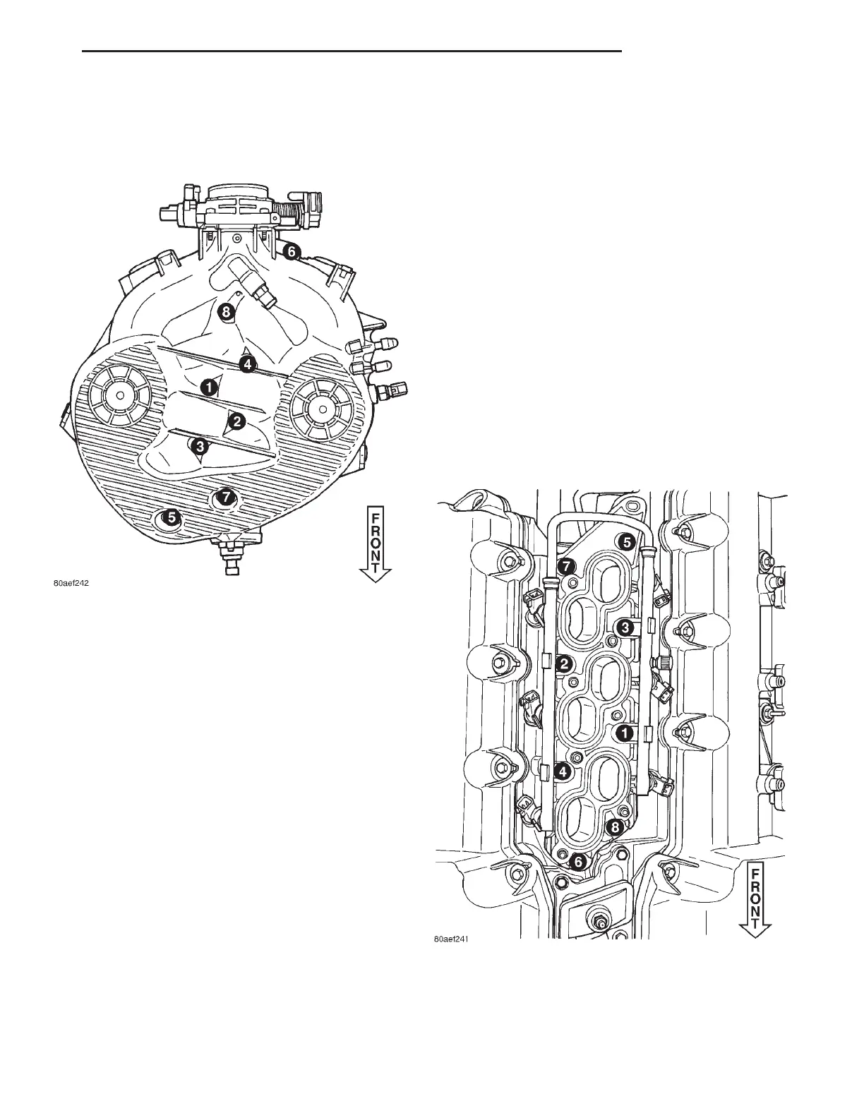
(3) Install manifold attaching bolts and tighten in
sequence shown in (Fig. 49) to 12 N·m (105 in. lbs.).
(4) Install engine name cover to manifold.
(5) Tighten upper fastener at throttle body support
bracket.
(6) Install EGR tube to manifold. Refer to EMIS-
SION CONTROL SYSTEMS for procedure.
(7) Connect speed control servo hose, PCV hose,
and vapor purge hoses.
(8) Connect electrical connectors to the following
components:
• Manifold Absolute Pressure (MAP) Sensor
• Intake Air Temperature (IAT) Sensor
• Throttle Position Sensor (TPS) Sensor
• Idle Air Control (IAC) Motor
• Manifold Tuning Valve (MTV)—(if equipped)
(9) Install throttle cable bracket.
(10) Install throttle and speed control cables to
bracket and throttle arm.
(11) Connect negative cable to battery remote
jumper terminal.
INTAKE MANIFOLD—LOWER
REMOVAL
(1) Release fuel system pressure. Refer to FUEL
SYSTEM for procedure.
(2) Remove upper intake manifold. Refer to proce-
dure in this section.
(3) Disconnect electrical connectors from the fuel
injectors.
(4) Remove fuel supply hose from fuel rail.
(5) Remove screw attaching fuel rail support
bracket to the throttle body support bracket.
(6) Remove bolts attaching fuel rail.
(7) Remove fuel rail and injectors as an assembly.
(8) Remove manifold attaching bolts.
(9) Remove lower manifold.
INSTALLATION
(1) Clean and inspect sealing surfaces of cylinder
head and manifold. Gaskets can be reused provided
they are free of cuts or tears.
Fig. 49 Upper Intake Manifold Tightening Sequence
Fig. 50 Lower Intake Manifold Tightening Sequence
LH 2.7L ENGINE 9 - 37
REMOVAL AND INSTALLATION (Continued)