(2) Position manifold on cylinder head surfaces.
NOTE: For ease of installing upper intake manifold,
install a bolt2–3turns to the rearmost attaching
hole of intake. This will properly position lower
manifold.
(3) Install fuel rail with injectors.
(4) Install manifold attaching bolts and tighten in
sequence shown in (Fig. 50) to 12 N·m (105 in. lbs.).
Remove bolt used for aligning manifold.
(5) Connect the fuel injector electrical connectors.
NOTE: Make sure fuel injectors are located in the
correct position, as upper intake manifold interfer-
ence could occur.
(6) Install screw attaching fuel rail support
bracket to the throttle body support bracket.
(7) Connect fuel supply hose to fuel rail.
(8) Install upper intake manifold. Refer to proce-
dure in this section.
(9) With the DRB scan tool use ASD Fuel System
Test to pressurize system to check for leaks.
CAUTION: When using the ASD Fuel System Test,
the Auto Shutdown (ASD relay will remain ener-
gized for 7 minutes or until the ignition switch is
turned to the OFF position, or Stop All Test is
selected.
EXHAUST MANIFOLD
RIGHT EXHAUST MANIFOLD
REMOVAL
(1) Disconnect negative cable from remote jumper
terminal.
(2) Remove air intake plenum and air filter hous-
ing.
(3) Remove bolt attaching battery cable housing
tube to transmission housing.
(4) Remove bolts attaching EGR tube from exhaust
manifold and EGR valve. Discard gaskets.
(5) Disconnect electrical connector and remove
exhaust manifold mounted oxygen sensor.
(6) Loosen and remove the manifold to catalytic
converter V-Band clamp.
NOTE: Do not reuse V-Band clamp.
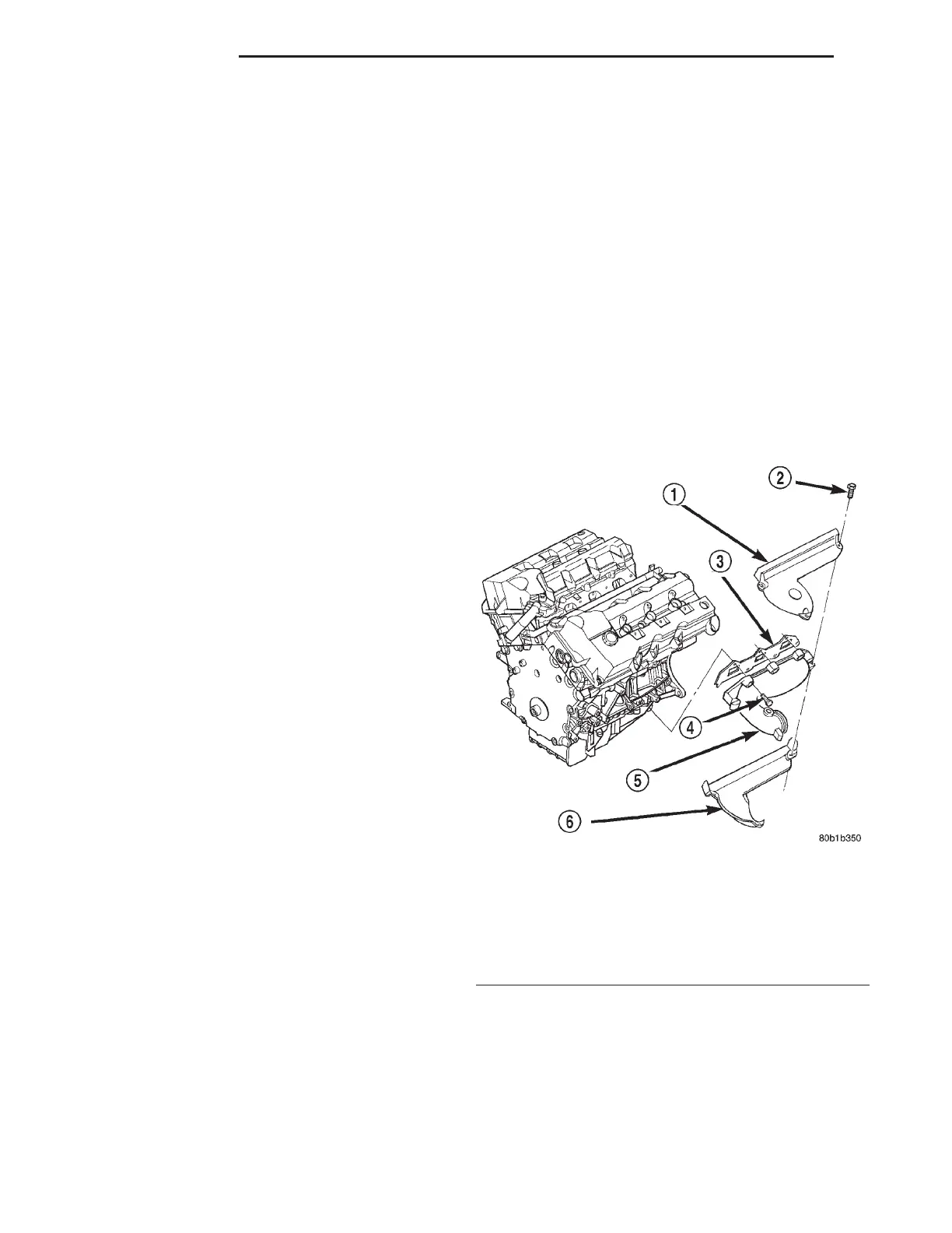
(7) Remove heat shield attaching screws and
remove heat shields (Fig. 51).
(8) Remove exhaust manifold attaching bolts and
remove manifold (Fig. 51).
INSTALLATION
(1) Install exhaust manifold and gasket. Tighten
bolts working from center outwards to 23 N·m (200
in. lbs.) (Fig. 51).
(2) Install heat shields. Tighten attaching screws
to 12 N·m (105 in. lbs.) (Fig. 51).
(3) Install a new V-Band clamp and tighten 10
N·m (100 in. lbs.).
(4) Install oxygen sensor and connect electrical
connector.
(5) Install EGR tube using new gaskets. Tighten
screws to 11 N·m (95 in. lbs.).
(6) Install bolt attaching battery cable housing
tube to transmission housing. Tighten bolt to 101
N·m (75 ft. lbs.).
(7) Install air intake plenum and air filter hous-
ing.
(8) Connect negative cable.
LEFT EXHAUST MANIFOLD
REMOVAL
(1) Disconnect negative cable from remote jumper
terminal.
(2) Raise vehicle on hoist.
(3) Remove exhaust system. Refer to EXHAUST
SYSTEM for procedure.
Fig. 51 Exhaust Manifold—2.7L Engine
1 – HEAT SHIELD
2 – BOLT
3 – GASKET
4 – BOLT
5 – EXHAUST MANIFOLD
6 – HEAT SHIELD
9 - 38 2.7L ENGINE LH
REMOVAL AND INSTALLATION (Continued)