POWER STEERING PUMP
TABLE OF CONTENTS
page page
DESCRIPTION AND OPERATION
POWER STEERING PUMP .................19
POWER STEERING FLUID RESERVOIR .......20
SERVICE PROCEDURES
POWER STEERING PUMP INITIAL
OPERATION ...........................20
REMOVAL AND INSTALLATION
SERVICE WARNINGS AND CAUTIONS ........21
POWER STEERING PUMP (2.7L ENGINE)......21
POWER STEERING PUMP (3.2L/3.5L ENGINE) . . 23
POWER STEERING FLUID RESERVOIR
(3.2L/3.5L Engine) .......................25
DISASSEMBLY AND ASSEMBLY
POWER STEERING FLUID RESERVOIR (2.7L
ENGINE)..............................25
POWER STEERING PUMP PULLEY...........26
SPECIFICATIONS
POWER STEERING PUMP FLOW
SPECIFICATIONS .......................28
POWER STEERING PUMP FASTENER
TORQUE SPECIFICATIONS ...............28
SPECIAL TOOLS
POWER STEERING PUMP .................28
DESCRIPTION AND OPERATION
POWER STEERING PUMP
DESCRIPTION
Hydraulic pressure for the operation of the power
steering system is provided by a belt driven rotary
power steering pump. The power steering pump is a
constant flow rate and displacement vane type pump.
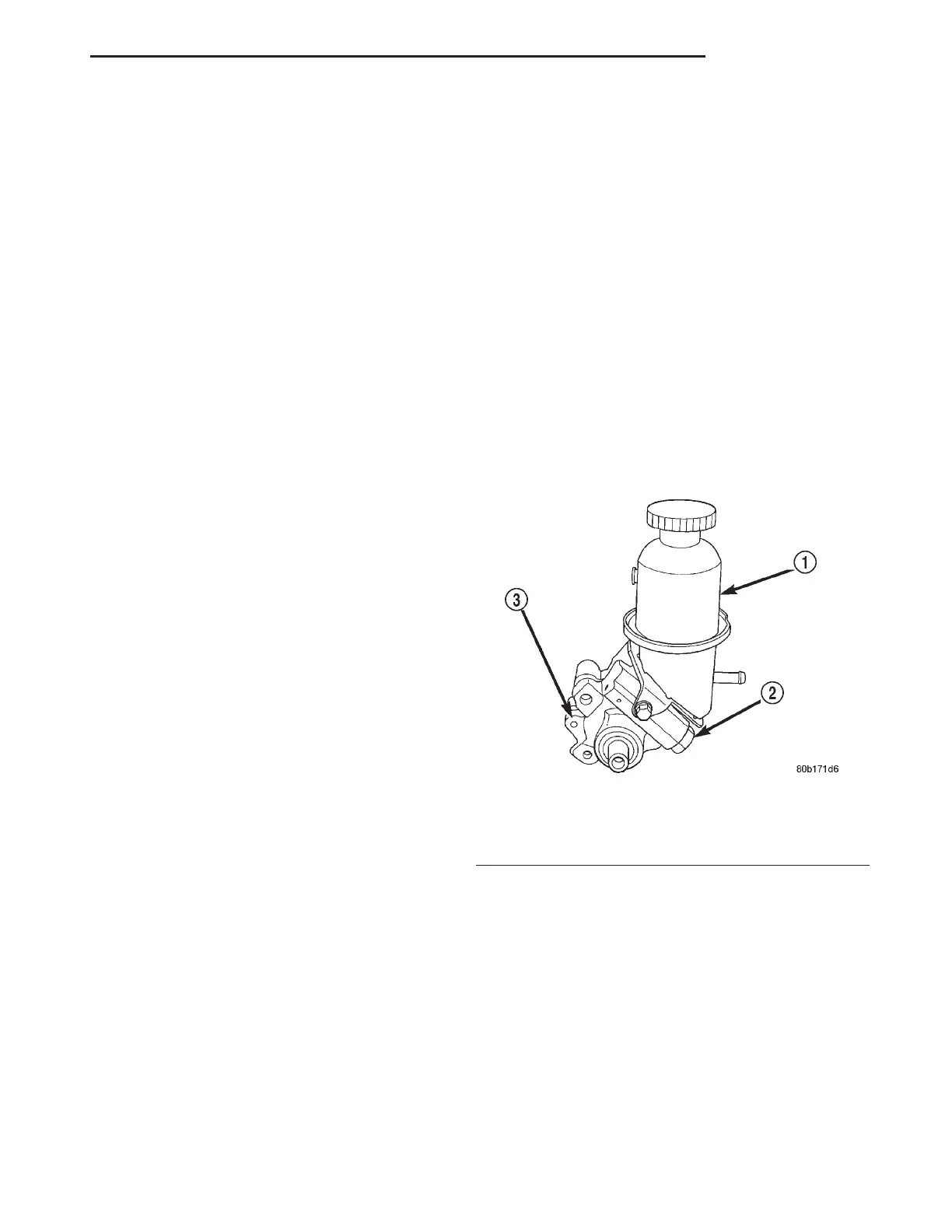
Vehicles equipped with the 2.7 liter engine use a
power steering pump that has an integral reservoir
for the power steering fluid (Fig. 1). Vehicles
equipped with the 3.2 liter or 3.5 liter engine use a
power steering pump (Fig. 2) that has a remotely
mounted reservoir for the power steering fluid.
Both power steering pumps mount to the front of
the engine on the driver’s side.
The service procedures for the power steering
pump are limited to the areas and components listed
below.
• Power steering fluid reservoirs, related compo-
nents and attaching hardware.
• Power steering pump pulley.
No repair procedures are to be done on the internal
components of the power steering pump. Repair of a
power steering fluid leak from any area of the power
steering pump is not allowed.
OPERATION
The Power steering pump operates as follows. A
belt driven pulley turns a shaft which drives a rotor.
Rectangular pumping vanes carried by the shaft
driven rotor move the fluid from the intake to the
cam ring pressure cavities. As the rotor begins to
turn, centrifugal force throws the vanes against the
inside surface of the cam ring to pickup residual oil.
This oil is then forced into the high pressure area. As
more oil is picked up by the vanes, the additional oil
is forced into the cavities of the thrust plate through
two crossover holes in the cam ring and pressure
plate. The crossover holes empty into the high pres-
sure area between the pressure plate and the hous-
ing end cover.
When the high pressure area of the power steering
pump is filled with power steering fluid, the fluid
flows under the vanes in the rotor slots, forcing the
vanes to follow the inside oval surface of the cam
ring. As the vanes reach the restricted area of the
cam ring, oil is forced out from between the vanes.
When excess oil flow is generated during high-speed
Fig. 1 Power Steering Pump (2.7L Engine)
1 – POWER STEERING FLUID RESERVOIR
2 – POWER STEERING PUMP PRESSURE FITTING
3 – POWER STEERING PUMP
LH STEERING 19 - 19

 Loading...


