The steering knuckle pivots with the strut assem-
bly on the lower control arm ball joint, allowing the
vehicle to be steered.
HUB AND BEARING (FRONT)
DESCRIPTION
The front wheel bearing and front wheel hub of
this vehicle are a hub and bearing unit type assem-
bly. This unit combines the front wheel mounting
hub (flange) and the front wheel bearing into a
sealed one piece unit. The hub and bearing is
mounted to the center of the steering knuckle and is
retained by three mounting bolts accessible from the
rear of the steering knuckle. The hub flange has five
wheel mounting studs.
The wheel mounting studs used to mount the tire
and wheel to the vehicle are the only replaceable
components of the hub and bearing assembly. Other-
wise, the hub and bearing is serviced only as a com-
plete assembly.
OPERATION
The hub and bearing has internal bearings that
allow the hub to rotate with the driveshaft and tire
and wheel. The five wheel mounting studs mount the
tire and wheel, and brake rotor to the vehicle.
LOWER CONTROL ARM
DESCRIPTION
The lower control arm is a steel forging with 2 rub-
ber bushings and a ball joint (Fig. 1). The bushing
isolating the lower control arm from the front cradle/
crossmember is a metal encased pivot bushing. The
bushing isolating the lower control arm from the ten-
sion strut is a solid rubber bushing. The lower con-
trol arm is bolted to the cradle/crossmember using a
bolt through the center of the pivot bushing. The ten-
sion strut is fastened through the center of the ten-
sion strut bushing and lower control arm. The lower
control arm ball joint connects to the steering
knuckle.
OPERATION
The lower control arm supports the lower end of
the steering knuckle and allows for the up and down
movement of the suspension during the jounce and
rebound travel.
BALL JOINT
DESCRIPTION
The ball joint is an integral part of the control arm
and has a non-tapered stud with a notch for clamp
(pinch) bolt installation. The stud is clamped and
locked into the steering knuckle leg using a clamp
(pinch) bolt.
The ball joint used in the lower control arm of this
vehicle is a sealed-for-life ball joint and requires no
maintenance lubrication. The ball joint cannot be ser-
viced separately from the lower control arm. If the
ball joint is determined to be defective it will require
replacement of the complete lower control arm. Refer
to DIAGNOSIS AND TESTING in this section for
proper testing of the ball joint.
NOTE: The ball joint does not require any type of
additional lubrication for the life of the vehicle. No
attempt should be made to ever add any lubrication
to the lower ball joint.
OPERATION
The ball joint is a pivotal joint on the lower control
arm that allows the knuckle to move up and down,
and turn with ease.
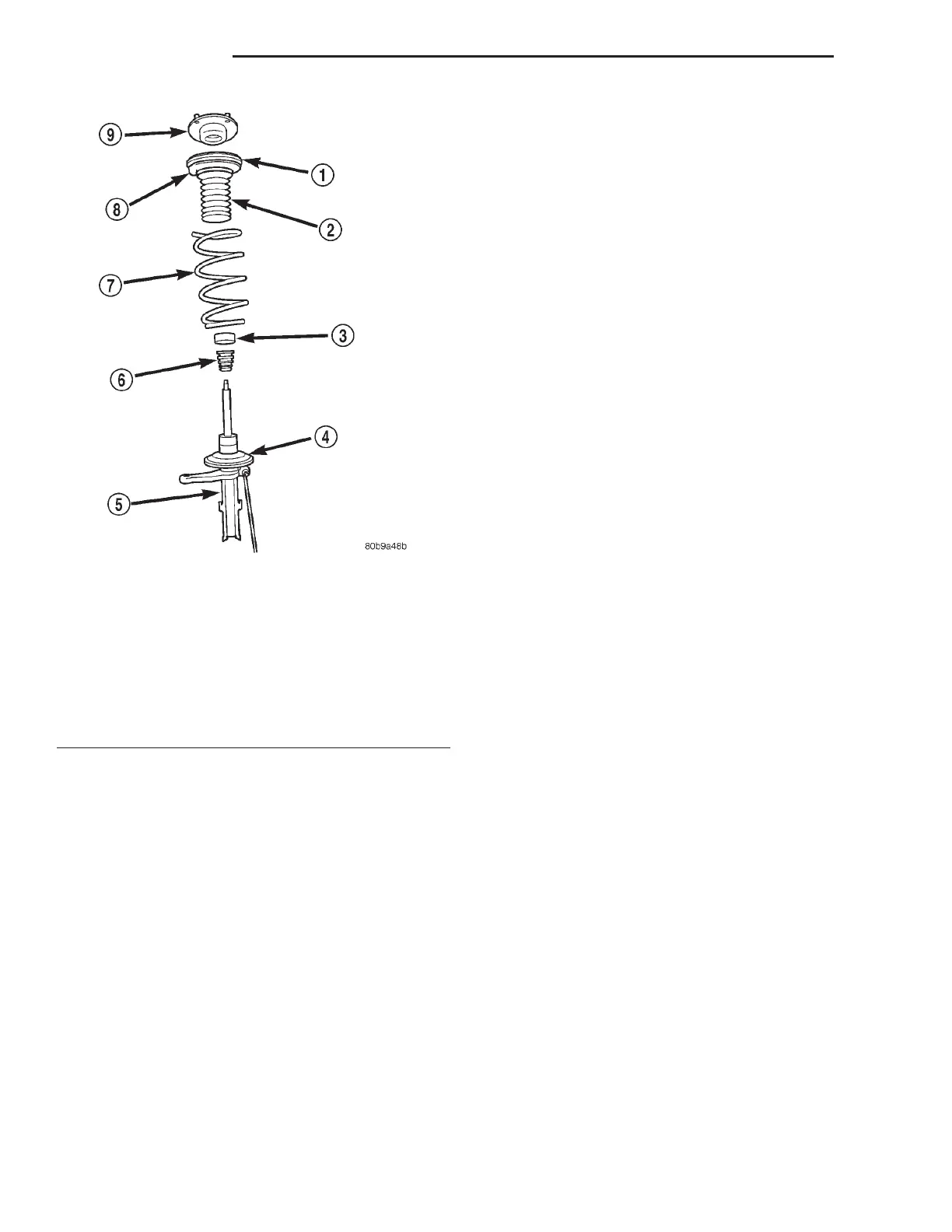
Fig. 2 Strut Assembly Components
1 – SEAT AND BEARING
2 – DUST SHIELD
3 – CUP
4 – LOWER SPRING ISOLATOR
5 – STRUT
6 – JOUNCE BUMPER
7 – COIL SPRING
8 – UPPER SPRING ISOLATOR
9 – UPPER MOUNT
2 - 12 SUSPENSION LH
DESCRIPTION AND OPERATION (Continued)