ELECTRO–MECHANICAL INSTRUMENT
CLUSTER
DESCRIPTION
The mechanical instrument cluster is an electro-
mechanical module which receives most of its infor-
mation via the Programmable Communication
Interface (PCI) bus.
There are three types of clusters.
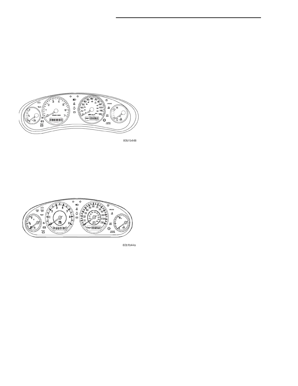
The Instrument Cluster for the Intrepid and Con-
corde are almost identical. The gauge and warning
lamp location and functionality are identical. The dif-
ference being, the Intrepid has white gauges with
black numbers with black gauge rings, and the Con-
corde has black gauges with white numbers and
chrome rings around the gauges.
• Speedometer
• Tachometer
• Odometer/trip odometer
• Fuel gauge
• Temperature gauge
• Electronic transmission range
The warning and information indicators include
the following:
• Check Engine
• Airbag
• Charging system
• Low oil pressure
• High temperature
• Low fuel
• Seat belt
• Cruise
• Brake/park brake
• High beam
• Turn signals
• Door Ajar
• Decklid Ajar
• ABS (optional)
• Traction Control Active (optional)
• Traction Control Off (optional)
• Low Washer Fluid
OPERATION
The gauges are the magnetic air-core type. When
the ignition switch is OFF, the gauge pointers should
rest at or below the low graduation.
DIAGNOSIS AND TESTING
CLUSTER DIAGNOSTIC PROCEDURE
As a quick diagnosis, the cluster will perform a
functional check of the odometer display, transmis-
sion range display and warning indicators after the
ignition is switched to RUN/START. If the cluster is
not receiving any PCI bus messages, the cluster will
appear non-functional and “no bus” will appear in
the odometer display.
A self-test of the cluster can also be initiated by
pressing and holding the odometer reset button and
switching the ignition from lock to unlock. The clus-
ter will then step through several displays for func-
tional verification.
If the cluster is not functioning properly, refer to
the proper Body Diagnostic Procedures Manual.
If the cluster is not receiving PCI bus messages,
refer to the pre-diagnostic test described in Body
Diagnostic Procedures Manual.
In order to diagnose the instrument cluster func-
tions, a DRB lllt scan tool and the proper Body Diag-
nostic Procedures Manual are required.
If the diagnostic procedure determines that a
replacement of an instrument cluster component is
required, refer to Cluster and Bezel Removal and
Installation in this section.
HEADLAMP SWITCH
Using an ohmmeter, test for resistance values
between the terminals of the switch as shown in the
Headlamp Switch Resistance table and (Fig. 4).
Fig. 2 Cluster – Intrepid/Concorde
Fig. 3 Cluster – LHS / 300M
8E - 2 INSTRUMENT PANEL SYSTEMS LH
DESCRIPTION AND OPERATION (Continued)