WHEELS
TABLE OF CONTENTS
page page
DESCRIPTION AND OPERATION
WHEEL .................................8
WHEEL COVER (BOLT-ON) ..................8
DIAGNOSIS AND TESTING
WHEEL INSPECTION.......................9
TIRE AND WHEEL RUNOUT .................9
SERVICE PROCEDURES
TIRE AND WHEEL BALANCE ................11
REMOVAL AND INSTALLATION
WHEEL COVER (BOLT-ON) .................12
TIRE AND WHEEL ASSEMBLY...............13
CLEANING AND INSPECTION
ALUMINUM WHEEL CARE..................15
SPECIFICATIONS
WHEEL SPECIFICATIONS ..................15
DESCRIPTION AND OPERATION
WHEEL
DESCRIPTION
Original equipment wheels are designed for proper
operation at all loads up to the specified maximum
vehicle capacity.
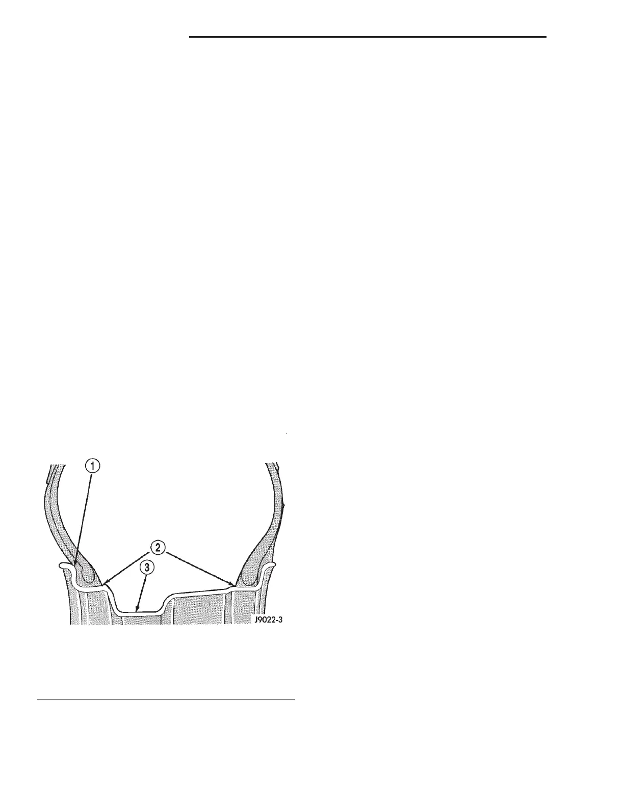
All models use steel or cast aluminum drop center
wheels. Every wheel has raised sections between the
rim flanges and rim drop well called safety humps
(Fig. 1).
Initial inflation of the tires forces the bead over
these raised sections. In case of air loss the raised
sections help hold the tire in position on the wheel
until the vehicle can be brought to a safe stop.
Cast aluminum wheels require special balance
weights to fit on the rim flange of the wheel and spe-
cial wheel clamps for the alignment equipment.
The wheel studs and nuts are designed for specific
wheel applications and must be replaced with equiv-
alent parts. Do not use replacement parts of lesser
quality or of a substitute design. All aluminum and
some steel wheels have wheel stud nuts with an
enlarged nose. This enlarged nose is necessary to
ensure proper retention of the wheels.
Before installing a wheel, remove any buildup of
corrosion on the wheel mounting surface.
WARNING: INSTALLING WHEELS WITHOUT GOOD
METAL-TO-METAL CONTACT COULD CAUSE LOOS-
ENING OF WHEEL LUG NUTS. THIS COULD
ADVERSELY AFFECT THE SAFETY AND HANDLING
OF YOUR VEHICLE.
WHEEL COVER (BOLT-ON)
DESCRIPTION
This vehicle uses a bolt-on type wheel cover (Fig.
2).
The wheel cover is bolted to the wheel using three
of the five wheel nuts (Fig. 3).
This bolt-on wheel cover cannot be removed from
the wheel until the three wheel nuts (Fig. 3) are
removed. The bolt-on wheel cover can be removed
with the remaining two wheel nuts remaining tight-
ened.
Fig. 1 Safety Rim
1 – FLANGE
2 – RIDGE
3 – WELL
22 - 8 TIRES AND WHEELS LH