fuel tank full of fuel, and no passenger or luggage
compartment load.
Vehicle height is not adjustable. If measurement is
not within specifications, inspect vehicle for bent or
weak suspension components. Compare parts tag on
suspect coil spring(s) to parts book and vehicle sales
code, checking for a match. Once removed from vehi-
cle, compare coil spring height to a correct new or
known good coil spring. The heights should vary if
the suspect spring is weak.
(1) Measure from the inboard edge of the wheel
opening fender lip directly above the wheel center
(spindle), to the floor or alignment rack surface.
(2) When measuring, maximum left-to-right differ-
ential is not to exceed 20 mm (0.79 in.).
(3) Compare measurements to specifications listed
in the following chart.
CURB HEIGHT SPECIFICATIONS
VEHICLE FRONT REAR
CONCORDE/LHS/300M
739 mm 6 20 mm 754 mm 6 20 mm
29.09 in. 6 0.79 in. 29.68 in. 6 0.79 in.
INTREPID
729 mm 6 20 mm 735 mm 6 20 mm
28.70 in. 6 0.79 in. 28.93 in. 6 0.79 in.
WHEEL ALIGNMENT
(1) Position the vehicle on an alignment rack.
(2) Perform a pre-wheel alignment inspection.
(3) Install all required alignment equipment on
the vehicle, per the alignment equipment manufac-
turer’s instructions.
NOTE: Prior to reading the vehicle’s alignment
readouts, the front and rear of vehicle should be
jounced. Induce jounce (rear first, then front) by
grasping the center of the bumper and jouncing
each end of vehicle an equal number of times. The
bumper should always be released when vehicle is
at the bottom of the jounce cycle.
(4) Read the vehicle’s current front and rear align-
ment settings. Compare the vehicle’s current align-
ment settings to the vehicle specifications for camber,
caster and toe-in. See Alignment Specifications in
this group of the service manual for the required
specifications.
(5) If the rear alignment is out of specification,
adjust it first, before proceeding to the front. Rear
camber and caster are not adjustable. If rear camber
is out of specification, check for damaged or bent rear
suspension components.
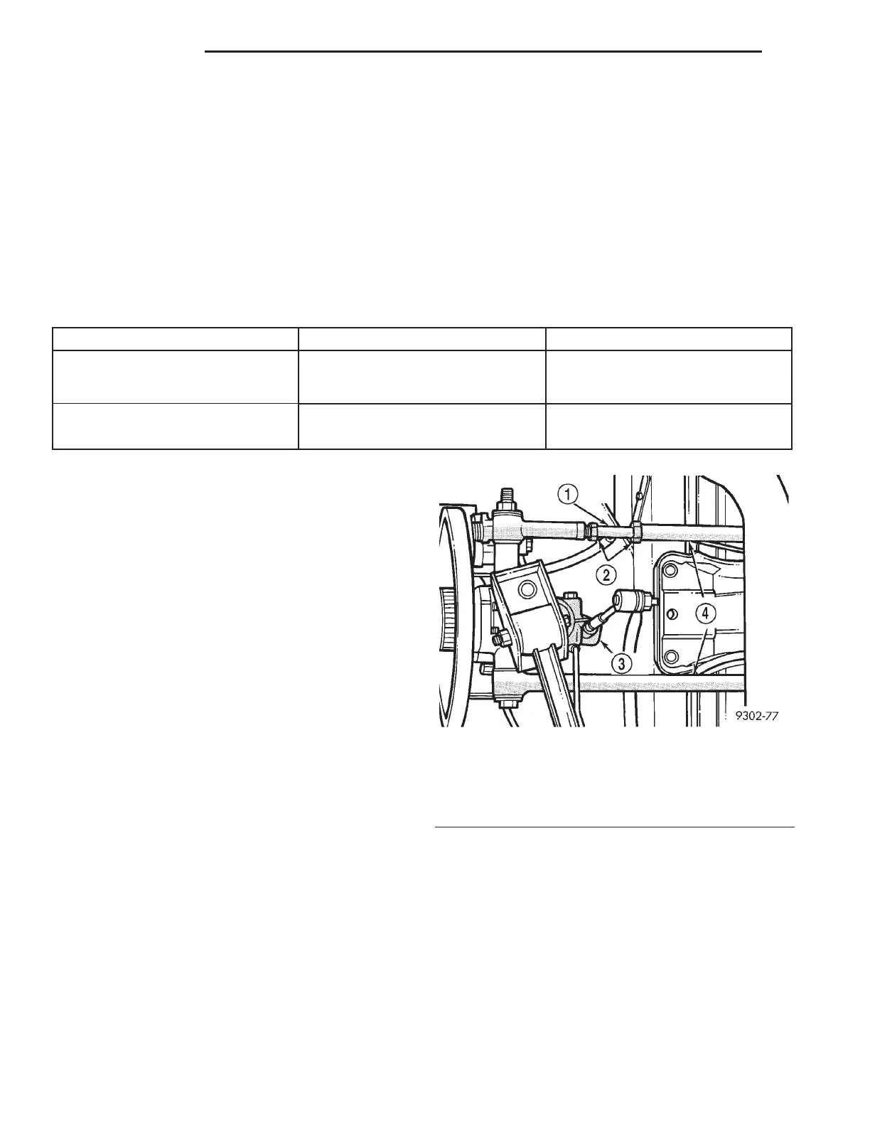
REAR WHEEL TOE ADJUSTMENT
(1) Loosen lateral link, adjustment link jam nuts
(Fig. 4). Rotate adjustment links as required to set
rear wheel Toe to specifications. Do not exceed the
maximum length dimensions of the lateral links
shown in (Fig. 5). Both dimensions must be
checked to ensure they do not exceed maxi-
mums allowed.
CAUTION: When setting rear toe-in on vehicle, the
maximum lengths of the adjustable lateral link at
the locations shown in (Fig. 5) must not be
exceeded. If these maximum lengths are exceeded,
inadequate retention of adjustment link to the inner
and outer link may result. Ensure that the adjust-
ment sleeve jam nuts are torqued to the required
specifications when the Toe setting procedure is
completed.
(2) Tighten lateral link, adjustment link lock-nuts
to 88 N·m (65 ft. lbs.) torque.
Fig. 4 Rear Wheel Toe Adjustment
1 – ADJUSTMENT LINK
2 – JAM NUTS
3 – SPINDLE
4 – LATERAL LINKS
2 - 6 SUSPENSION LH
SERVICE PROCEDURES (Continued)