(2) Press momentarily and release memory switch
S.
(3) Press momentarily and release memory switch
1or2.
(4) To program the second driver’s position, repeat
the above procedure using the remaining memory
switch.
(5) To recall either of the programmed positions
momentarily press and release either memory selec-
tor switch 1 or 2.
DIAGNOSIS AND TESTING
GLIDE FEATURE
If seat isn’t sliding forward properly:
(1) First use the DRB scan tool to check whether
glide feature is enabled or not. Enable glide feature if
disabled, and go to Step 2.
(2) Turn the ignition ON and then back OFF.
Remove the key. If seat glides rearward, reinsert key
and turn to ON position. If seat doesn’t glide for-
ward, go to Step 3, otherwise the problem has been
fixed. If Learn Guard Bands test has been run and
problem persists, then replace MHSMM.
(3) Now run Learn Guard Bands Diagnostic test as
shown in this section, and go through Step 2 again.
SERVICE PROCEDURES
REMOTE KEYLESS ENTRY (RKE)
The MHSMM interfaces with the RKE vial the
Programmable Communication Interface (PCI) bus.
The proper procedure of setting and recalling a mem-
ory position using the RKE is as follows:
(1) Press memory switch 1 and release to recall
memory position 1.
(2) Adjust the seat, recliner and side view mirrors
to the desired position.
(3) Press momentarily and release memory switch
S.
(4) Press momentarily and release memory switch
1or2.
(5) Press and release the UNLOCK button on one
of the RKE transmitters. Do NOT press any switch
for 10 seconds.
(6) Set radio station presets.
To program the second driver’s position, repeat the
above procedure using memory switch 2. The second
RKE transmitter can be programmed in the fashion.
To recall either of the programmed positions
momentarily press and release either memory selec-
tor switch 1 or 2. If using RKE, just press and
release the UNLOCK button on the proper transmit-
ter for either position 1 or 2.
A recall is possible any time the vehicle transmis-
sion is in PARK. This condition is monitored by the
Body Control Module (BCM).
NOTE: The module will abort a recall if the trans-
mission is moved out of park or if any seat move-
ment is activated whether manually or by memory
recall.
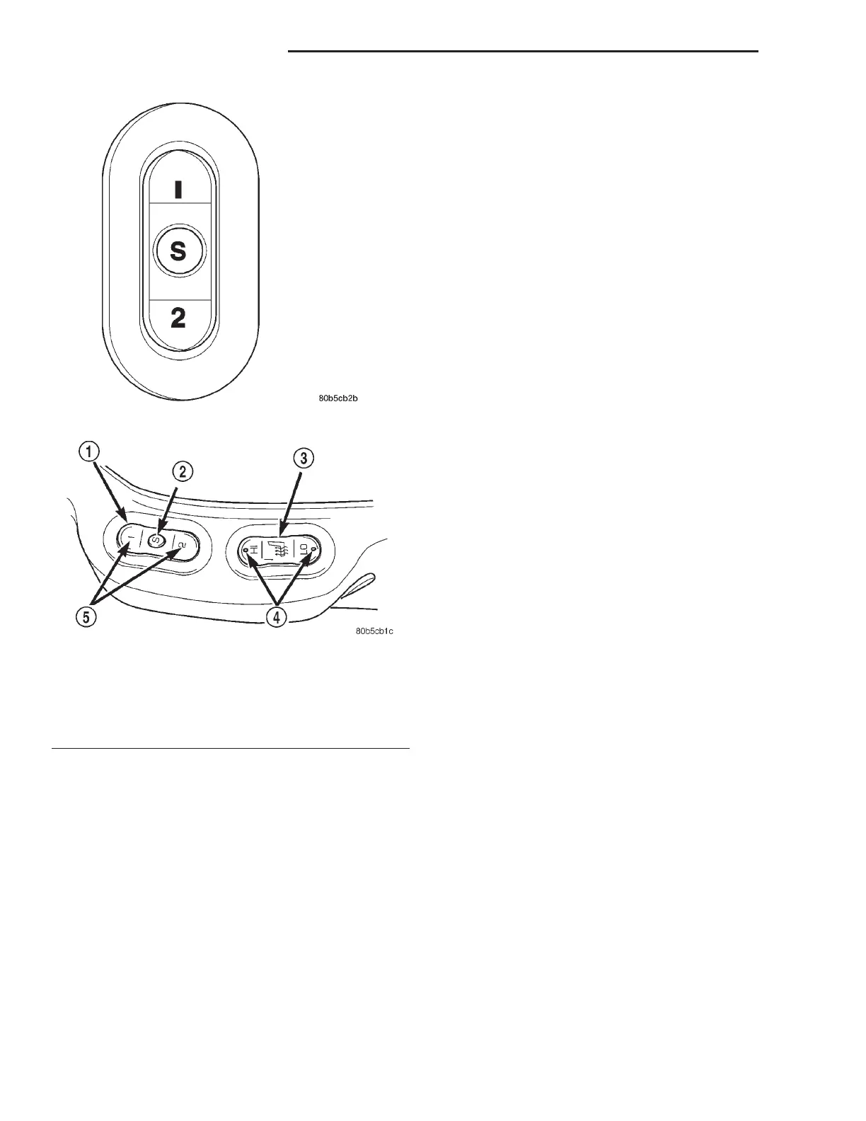
Fig. 1 Memory Selector Switch
Fig. 2 Memory Selector Switch Location
1 – MEMORY SELECTOR SWITCH
2 – DRIVER POSITION SET
3 – HEATED SEAT SWITCH
4 – LED’S
5 – DRIVER POSITION
8R - 6 POWER SEAT SYSTEMS LH
DESCRIPTION AND OPERATION (Continued)