the garter spring is intact around the top of the rub-
ber seal. Install valve springs, valve retainers.
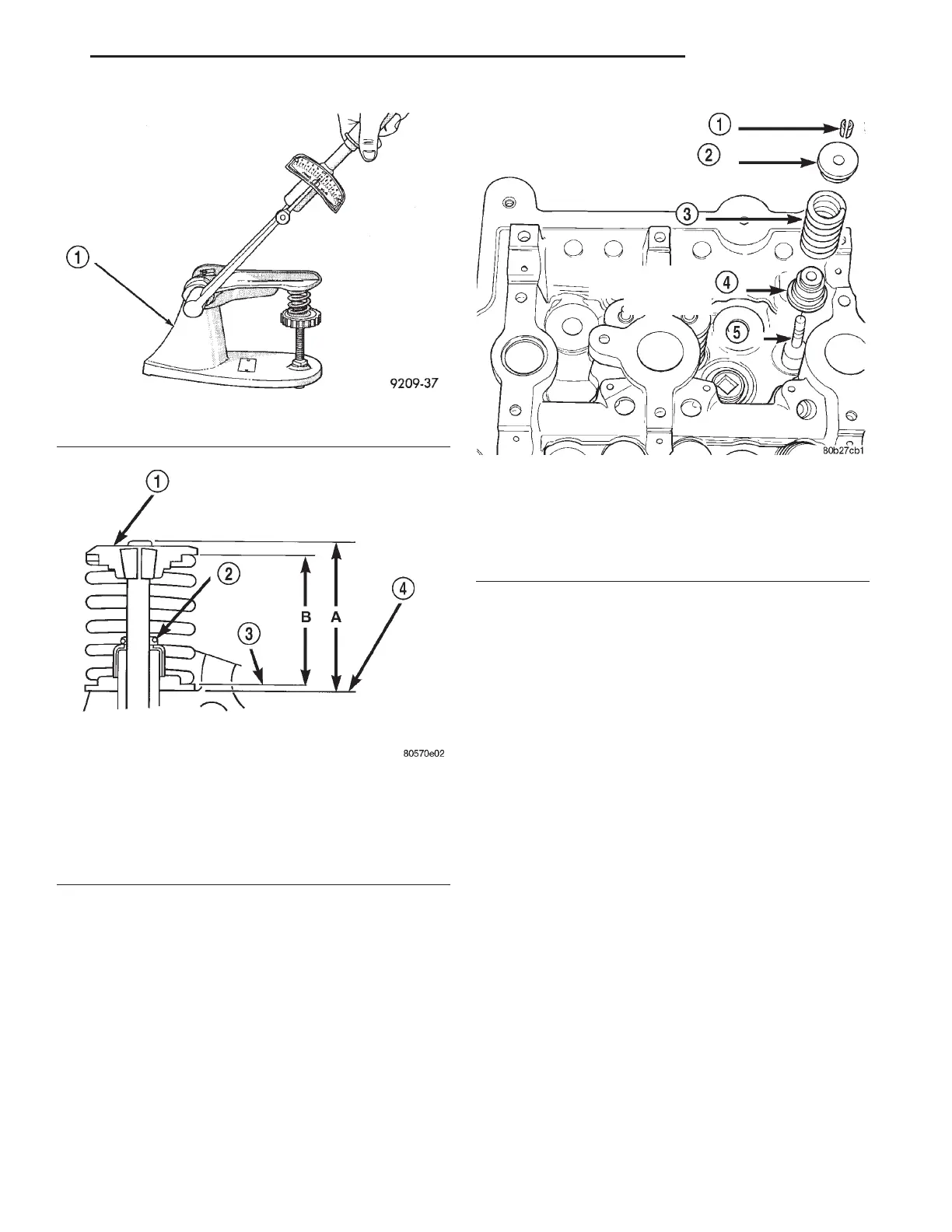
(4) Compress valve springs with a valve spring
compressor install locks and release tool. If valves
and/or seats are reground, measure the
installed height of springs (B) (Fig. 35), make
sure measurements are taken from top of
spring seat to the bottom surface of spring
retainer. If height is greater than 38.75 mm (1.5256
in.), install a 0.762 mm (0.030 in.) spacer in head
counterbore under the valve spring seat to bring
spring height back within specification.
ENGINE TIMING—VERIFICATION
Correct timing is critical for the NON free-wheel-
ing designed, 2.7L engine. Engine timing can be ver-
ified by using the following procedures:
(1) Remove cylinder head covers. Refer to proce-
dure in this section.
(2) Rotate engine until number one cylinder is at
TDC on the EXHAUST stroke.
(3) View the intake camshaft sprocket timing
mark. The mark should be 90° from the cylinder
head cover sealing surface (Fig. 37) on both right and
left cylinder banks.
(4) Count chain pins from the mark on the intake
camshaft towards the exhaust camshaft. Engine is
timed correctly when there are 12 chain pins
between the timing marks on the intake camshaft
and exhaust camshaft (Fig. 37).
(5) If marks are not correctly aligned, proceed to
Camshafts, Timing Chain and Sprockets, Removal
and Installation procedures.
Fig. 34 Testing Valve Spring with Tool C-647
1 – SPECIAL TOOL C-647
Fig. 35 Checking Valve Tip Height and Valve Spring
Installed Height
1 – SPRING RETAINER
2 – GARTER SPRING
3 – VALVE SPRING SEAT TOP
4 – CYLINDER HEAD SURFACE
Fig. 36 Valve Seal and Spring
1 – VALVE RETAINING LOCKS
2 – VALVE SPRING RETAINER
3 – VALVE SPRING
4 – VALVE SEAL AND VALVE SPRING SEAT ASSEMBLY
5 – VALVE
LH 2.7L ENGINE 9 - 29
SERVICE PROCEDURES (Continued)