INTAKE MANIFOLD
DESCRIPTION
The two piece intake manifold is made of a com-
posite material. The intake manifold features a com-
pact, low rumble design that maximizes engine
performance while minimizing induction noise. A
manifold tuning valve (MTV) is used on some models.
OPERATION
The intake air plenum chambers absorb air pulsa-
tions created during each cylinder’s intake stroke.
The manifold tuning valve (if equipped) connects
both sides of the intake manifold plenums at specific
engine speeds to maximize low RPM torque, without
reducing high RPM power.
EXHAUST MANIFOLD
DESCRIPTION
The exhaust manifolds are a log style design and
made of cast nodular iron (Fig. 10). The outlets are
designed for V-band clamp attachment of close cou-
pled catalytic converters.
ENGINE LUBRICATION
DESCRIPTION
The lubrication system is a full-flow filtration,
pressure feed type. The oil pump body is mounted to
the engine block. The pump inner rotor is driven by
the crankshaft. A structural windage tray is used to
increase power by minimizing oil windage at high
engine RPM. An engine oil cooler is used on some
models.
OPERATION
Oil from the oil pan is pumped by an geroter type
oil pump directly coupled to the crankshaft (Fig. 11).
Oil pressure is controlled by a relief valve mounted
inside the oil pump housing. See (Fig. 11), (Fig. 12),
and (Fig. 13) for engine oil lubrication circuits.
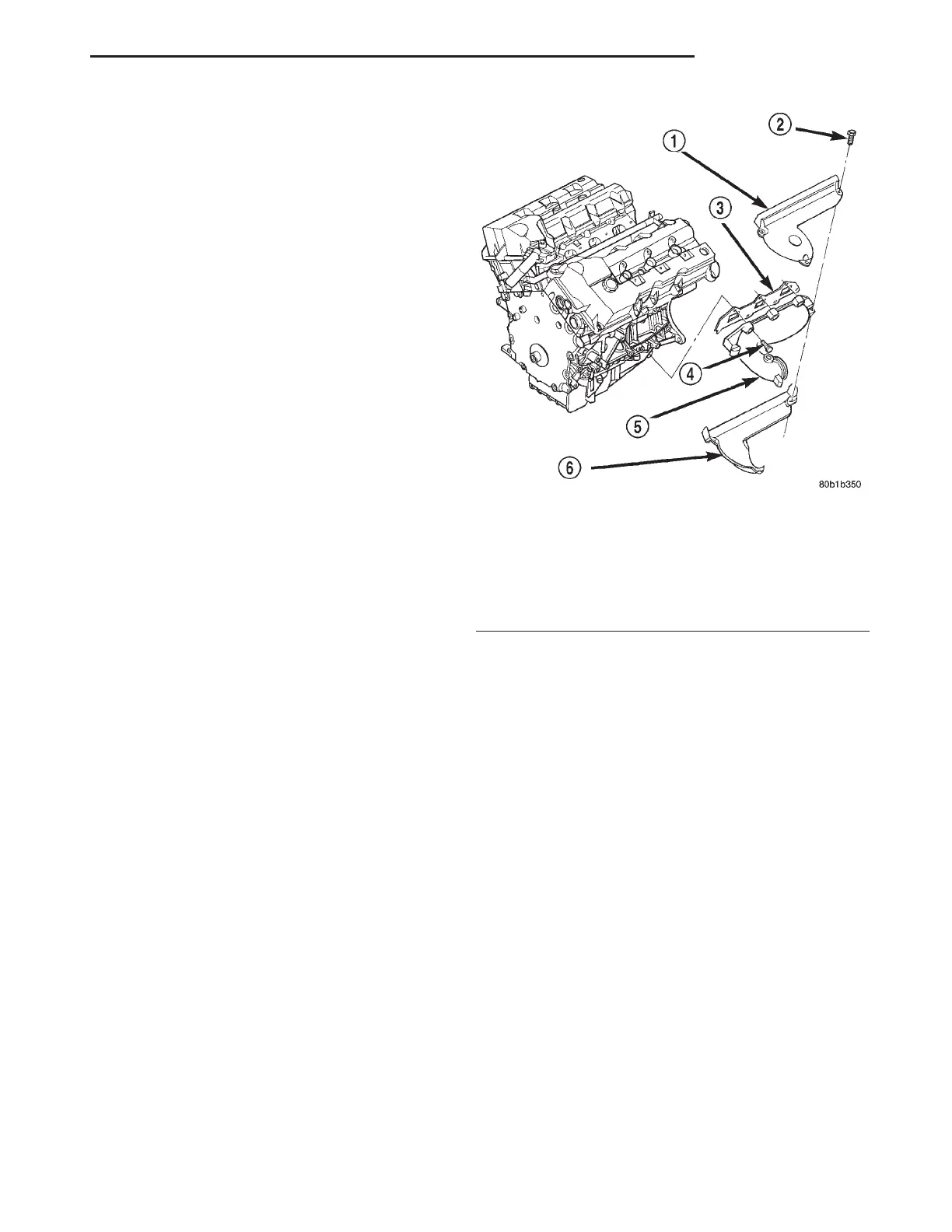
Fig. 10 Exhaust Manifold
1 – HEAT SHIELD
2 – BOLT
3 – GASKET
4 – BOLT
5 – EXHAUST MANIFOLD
6 – HEAT SHIELD
LH 2.7L ENGINE 9 - 9
DESCRIPTION AND OPERATION (Continued)