(3) Tighten cylinder head cover attaching bolts and
double-ended studs to 12 N·m (105 in. lbs.).
(4) Connect all electrical connectors and harness
clips.
(5) Install ignition coil capacitors and fasteners.
(6) Install upper intake manifold. Refer to proce-
dure in this section.
CAMSHAFT
REMOVAL
(1) Remove the primary timing chain. Refer to pro-
cedure in this section.
(2) Remove secondary chain tensioner mounting
bolts.
NOTE: Camshaft bearing caps have been marked
during engine manufacturing. For example, number
one exhaust camshaft bearing is marked “1E>”
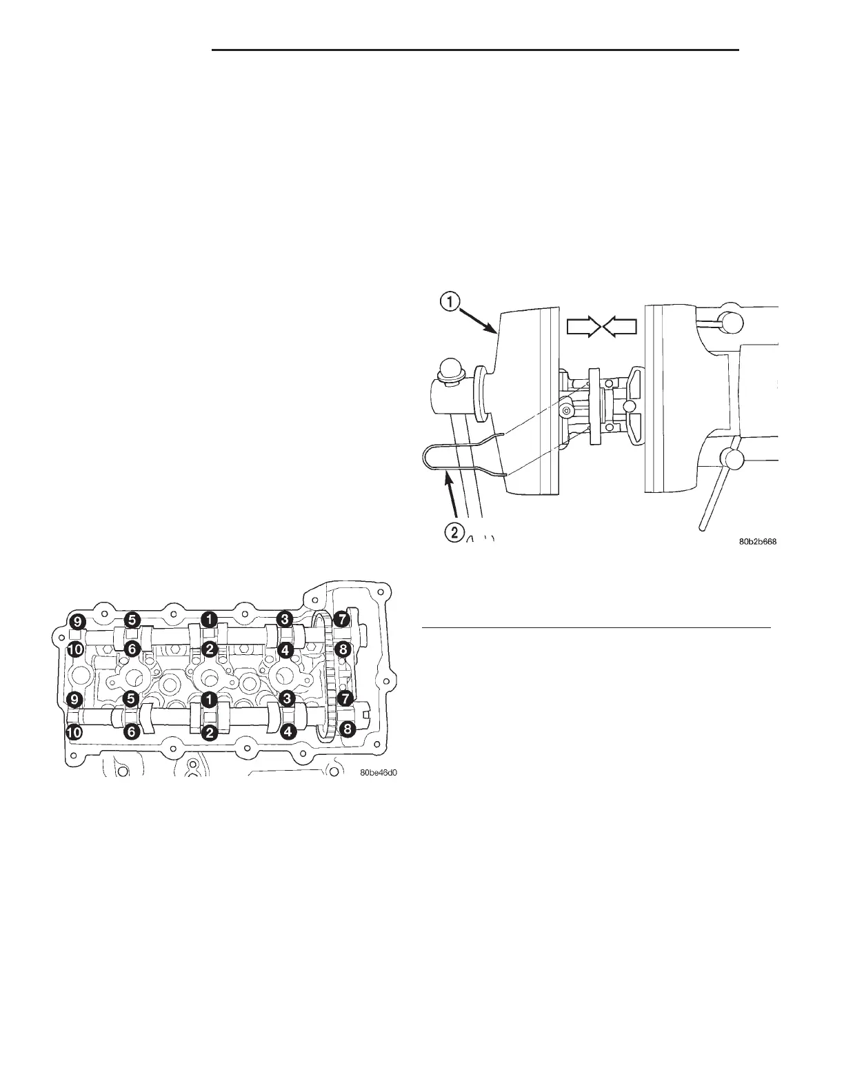
(3) Slowly loosen camshaft bearing cap bolts in
reverse order of installation (Fig. 54).
(4) Remove camshaft bearing caps.
(5) Remove camshafts, secondary chain, and ten-
sioner together as an assembly.
(6) Remove tensioner and camshaft chain from
camshafts.
(7) Inspect camshafts. Refer to Cleaning and
Inspection in the Section.
INSTALLATION
CAUTION: When the timing chain is removed and
the cylinder heads are installed, DO NOT rotate the
camshafts or crankshaft without first locating the
proper crankshaft position. Failure to do so will
result in valve and/or piston damage.
(1) Assemble camshaft chain on the cams. Ensure
that plated links are facing toward the front. Align
the plated links to the dot on the camshaft sprockets
(Fig. 56).
(2) If camshaft chain tensioner is already in the
compressed and locked position, proceed to step (4).
(3) When the camshaft chain tensioner is removed,
it is necessary to compress and lock the tensioner
using the following procedures:
(a) Place tensioner into a soft jaw vise (Fig. 55).
(b) SLOWLY compress tensioner until fabricated
lock pin or the equivalent can be inserted into the
locking holes.
(c) Remove compressed and locked tensioner
from the vise.
(4) Insert the compressed and locked camshaft
chain tensioner in-between the camshafts and chain.
(5) Rotate the cams so that the plated links and
dots are facing the 12:00 O’clock position (Fig. 56).
(6) Install cams to cylinder head. Ensure that
rocker arms are correctly seated and in proper posi-
tions.
(7) Install camshaft bearing caps. Ensure that
bearing caps are installed in same position as
removed.
(8) Tighten cam bearing cap bolts gradually in
sequence shown in (Fig. 54) to 12 N·m (105 in. lbs.).
(9) Install secondary chain tensioner bolts and
tighten to 12 N·m (105 in. lbs.).
(10) Remove locking pin from secondary tension-
ers.
(11) Measure camshafts end play by mounting a
dial indicator to a stationary point on cylinder head.
Locate the probe perpendicular against the end of
camshaft being checked. Move camshaft all the way
to the rear of its travel. Zero the dial indicator. Move
camshaft forward to limits of travel and read the dial
indicator (Fig. 57).
Fig. 54 Camshaft Bearing Cap Tightening Sequence
Fig. 55 Locking Camshaft (Secondary) Chain
Tensioner
1 – VISE
2 – LOCK PIN
9 - 40 2.7L ENGINE LH
REMOVAL AND INSTALLATION (Continued)