CRANKSHAFT END PLAY—CHECKING
(1) Mount a dial indicator to a stationary point at
front of engine. Locate the probe perpendicular
against nose of crankshaft (Fig. 32).
(2) Move crankshaft all the way to the rear of its
travel.
(3) Zero the dial indicator.
(4) Move crankshaft all the way to the front and
read the dial indicator. Refer to Engine Specifica-
tions.
VALVE AND VALVE SEAT—REFACING
The intake and exhaust valves have a 44.5 to 45
degree face angle. The valve seats have a 45 to 45.5
degree face angle. The valve face and valve seat
angles are shown in (Fig. 33).
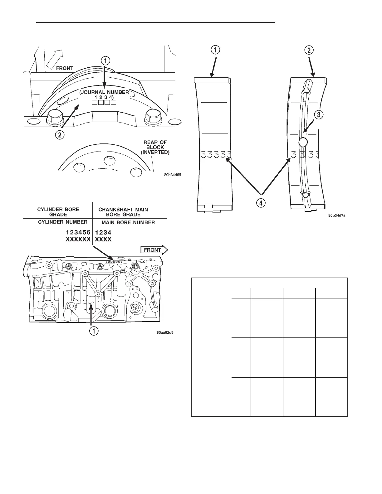
Fig. 29 Crankshaft Main Journal Grade Marking
Location
Fig. 30 Cylinder Block Main Bore Grade Marking
Location
Fig. 31 Main Bearing Grade Marks
1 – LOWER MAIN BEARING
2 – UPPER MAIN BEARING
3 – OIL FEED HOLE AND GROOVE
4 – GRADE SELECTION INK MARKS
MAIN BEARING SELECTION CHART—2.7L
Main Bearing Bore Grade Mark
123
Crankshaft
Main
Journal
Grade Mark
1
(3)
standard
(2)
+0.003
mm
(+0.0002
in.)
(1)
+0.006
mm
(+0.0003
in.)
2
(4)
-0.003
mm
(-0.0002)
(3)
standard
(2)
+0.003
mm
(+0.0002
in.)
3
(5)
-0.006
mm
(-0.0003
in.)
(4)
-0.003
mm
(-0.0002
in.)
(3)
standard
LH 2.7L ENGINE 9 - 27
SERVICE PROCEDURES (Continued)