specification. Then repeat the tightening sequence to
the full specified torque of 129 N·m (95 ft. lbs.).
(11) Remove jackstands or lower hoist.
CAUTION: Before moving vehicle, pump the brake
pedal several times to insure the vehicle has a firm
brake pedal to adequately stop the vehicle.
(12) Road test the vehicle and make several stops
to wear off any foreign material on the brakes and to
seat the brake shoe linings.
PARKING BRAKE LEVER (PEDAL) AND FRONT
CABLE ASSEMBLY
REMOVAL
NOTE: The parking brake lever assembly on this
vehicle is serviced with the front cable installed on
it. They should be removed, replaced, and installed
as an assembly.
(1) Remove remote ground cable from ground stud
on shock tower. Then correctly isolate ground cable
from vehicle by installing isolator on stud (Fig. 69).
(2) Raise the vehicle using a frame contact type
hoist or correctly supported on jackstands. See Hoist-
ing in the Lubrication and Maintenance group of this
service manual for the required lifting procedure for
this vehicle.
(3) Loosen the park brake tensioner adjuster nut,
in front of the rear crossmember, until tension is
removed from cables.
(4) Disconnect the cable connector between the
front and intermediate cable.
(5) Lower the vehicle to the ground.
(6) Remove the driver’s door opening sill cover.
(7) Remove the driver’s side kick panel.
(8) Remove the fuse panel cover from the left end
of the instrument panel (Fig. 70).
(9) Remove the 2 screws behind the fuse panel
cover, (Fig. 71) attaching the lower instrument panel
cover to the instrument panel mounting bracket.
(10) Remove the lower instrument panel cover
from the instrument panel. It is attached by retain-
ing clips along the top and right edge.
Fig. 69 Correctly Isolated Remote Ground Cable
1 – CABLE ISOLATOR
2 – GROUND STUD
3 – GROUND CABLE
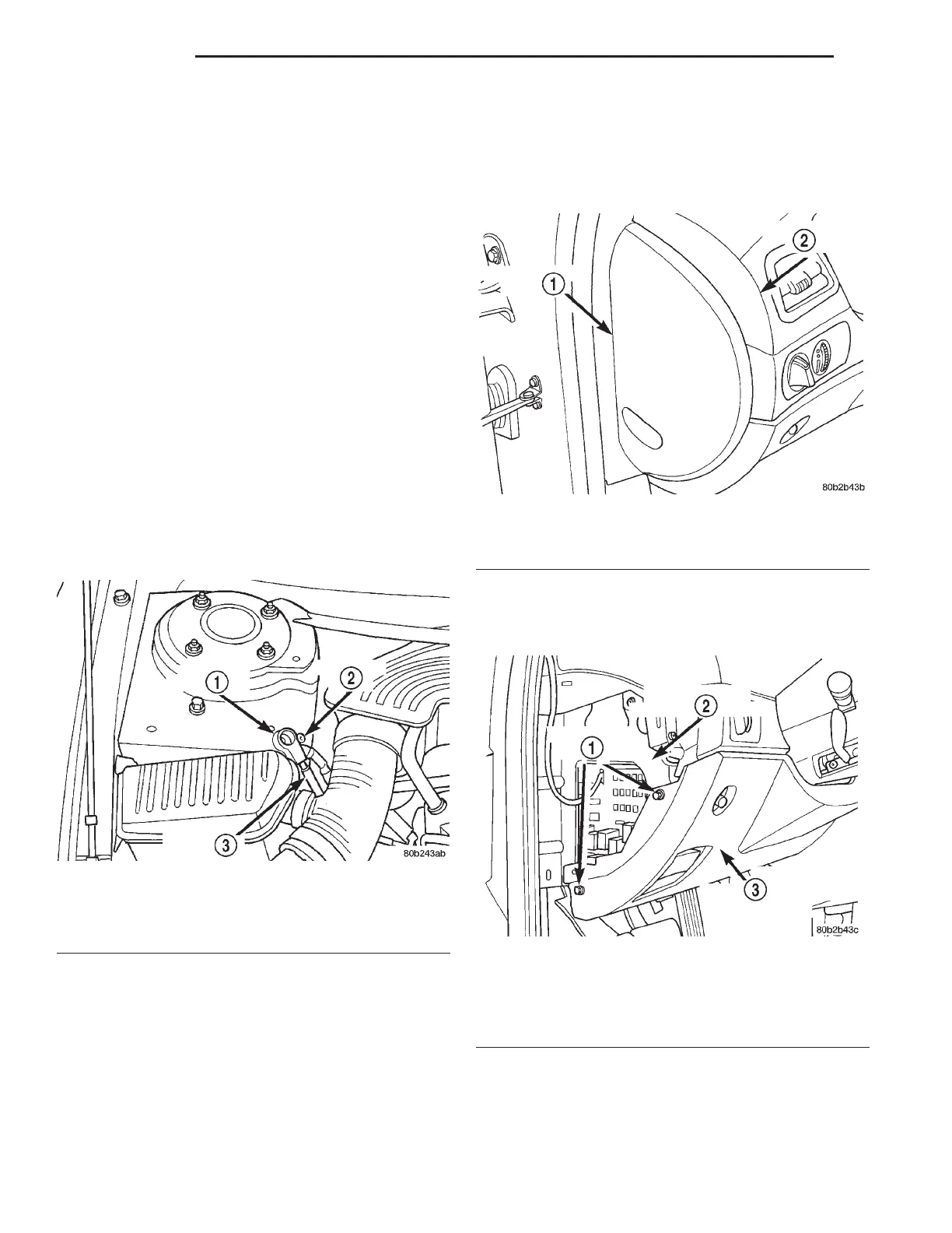
Fig. 70 Fuse Panel Cover
1 – FUSE PANEL COVER
2 – INSTRUMENT PANEL
Fig. 71 Lower Instrument Panel Cover Mounting
Screws
1 – MOUNTING SCREWS
2 – INSTRUMENT PANEL BRACKET
3 – LOWER INSTRUMENT PANEL COVER
5 - 38 BRAKES LH
REMOVAL AND INSTALLATION (Continued)