INSTALLATION
(1) Install the ICU back in the vehicle and attach
it to its mounting bracket. Tighten the 3 ICU mount-
ing bolts to 11 N·m (97 in. lbs.).
(2) Reinstall the inner fender splash shield.
(3) reinstall the tire and wheel assembly.
(4) Lower the vehicle.
CAUTION: Before installing the 25-way connector
in the CAB be sure that the seal is properly
installed in the connector.
(5) Install the 25-way connector into the socket on
the CAB. The connector is installed using the follow-
ing procedure. Position the 25-way connector in the
socket on the CAB and carefully push it onto CAB as
far as it will go. When connector is fully seated into
the CAB socket push in the connector lock (Fig. 16)
as far as it will go. This will pull the 25-way connec-
tor into the socket on the CAB and lock it in the
installed position.
(6) Install the 4 chassis brake tubes on the HCU
(Fig. 15). Tighten the chassis brake tubes to 17 N·m
(145 in. lbs.).
(7) Install the primary and secondary brake lines
from the master cylinder on the HCU (Fig. 15).
Tighten the primary and secondary brake tubes to 17
N·m (145 in. lbs.).
(8) Reinstall the transmission controller (Fig. 14).
(9) Reattach the washer bottle filler neck to the
radiator support.
(10) Reinstall the speed control servo to its mount-
ing studs and radiator support.
(11) Remove brake pedal positioning tool.
(12) Install the remote ground cable onto the
ground stud located on left shock tower. Install the
remote ground cable attaching nut and tighten to a
torque of 28 N·m (250 in. lbs.).
NOTE: The ICU may need to be initialized, using
the DRB scan tool, after installation.
(13) Bleed the base brakes and the ABS brakes
hydraulic system. Refer to the Bleeding ABS System
in this section of the manual for the proper bleeding
procedure.
(14) Road test vehicle to ensure proper operation
of the base and ABS systems.
WHEEL SPEED SENSOR (FRONT)
REMOVAL
(1) Raise vehicle on jack stands or centered on a
frame contact type hoist. See Hoisting in the Lubri-
cation and Maintenance section of this manual, for
the required lifting procedure to be used for this
vehicle.
(2) Remove the tire and wheel assembly from the
vehicle.
(3) Remove bolt securing the speed sensor cable
routing bracket (Fig. 17) to the strut assembly.
(4) Remove retainer, holding the speed sensor seal-
ing grommet, from the inner fender. pull the grom-
met out, then unplug the speed sensor cable from the
vehicle wiring harness
(5) Remove bolt attaching speed sensor to steering
knuckle. Carefully remove speed sensor head from
steering knuckle. If sensor is seized in place by cor-
rosion, tap the edge of the sensor ear with a hammer
and brass punch (Fig. 18), working it side to side.
CAUTION: If speed sensor head locating pin has
seized to the steering knuckle, do not attempt to
remove speed sensor head by grasping with pliers
and turning. This will damage the speed sensor
head. Use only the following procedure.
INSTALLATION
CAUTION: Proper installation of wheel speed sen-
sor cables is critical to continued system operation.
Be sure that cables are installed in retainers. Fail-
ure to install cables in retainers as shown in this
section may result in contact with moving parts
and/or over extension of cables, resulting in an
open circuit.
(1) Connect the wheel speed sensor cable connector
to the vehicle wiring harness.
(2) Install the speed sensor cable assembly grom-
met into the front inner fender. Install speed sensor
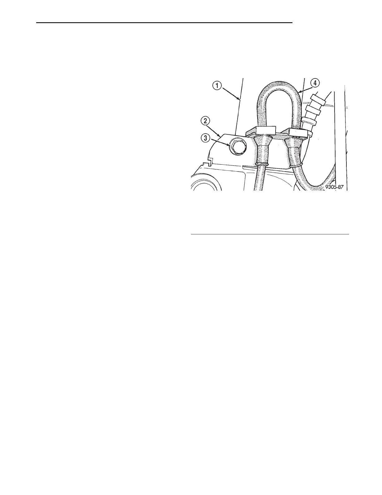
Fig. 17 Speed Sensor Cable Routing Bracket
1 – STRUT ASSEMBLY
2 – ROUTING BRACKET
3 – SCREW
4 – SPEED SENSOR CABLE
LH BRAKES 5 - 71
REMOVAL AND INSTALLATION (Continued)