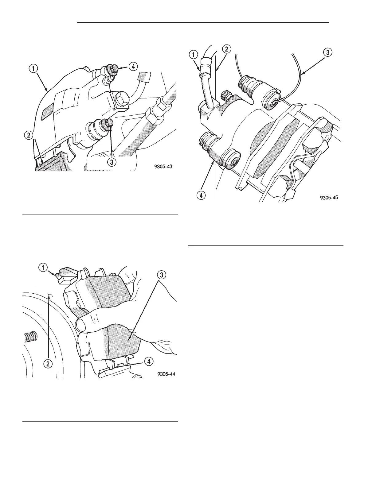
(3) Remove the 2 caliper assembly to adapter
guide pin bolts (Fig. 63).
(4) Remove caliper from adapter using the follow-
ing procedure. First rotate top of caliper away from
adapter. Then lift caliper assembly off bottom abut-
ment of adapter to remove it from the vehicle (Fig.
64).
(5) Support caliper assembly firmly from rear strut
to prevent weight of caliper from damaging the flex-
ible brake hose (Fig. 65).
(6) Remove the rear rotor from the hub by pulling
it straight off the wheel mounting studs (Fig. 66).
(7) Remove outboard brake shoe, by prying brake
shoe retaining clip over raised area on caliper and
sliding the shoe off the caliper (Fig. 67).
(8) Pull inboard brake shoe away from piston,
until the retaining clip is free from the cavity in the
piston (Fig. 68).
CALIPER INSPECTION
Check for piston seal leaks (brake fluid in and
around boot area and inboard lining) and for any
ruptures of the piston dust boot. If boot is damaged,
or fluid leak is visible, disassemble caliper assembly
and install a new seal and boot, (and piston if
scored). Refer to procedures titled Disc Brake Caliper
Disassembly.
Check the caliper dust boot and caliper pin bush-
ings to determine if they are in good condition.
Replace if they are damaged, dry, or found to be brit-
tle. Refer to Cleaning And Inspection Of Brake Cali-
per.
INSTALLATION
NOTE: Step 1 below is only required when install-
ing a caliper after new brake shoes have been
installed.
Fig. 63 Caliper Guide Pin Bolts
1 – CALIPER ASSEMBLY
2 – ADAPTER
3 – CALIPER ASSEMBLY ATTACHING BOLT
4 – CALIPER ASSEMBLY ATTACHING BOLT
Fig. 64 Removing / Installing Caliper
1 – ADAPTER
2 – BRAKING DISC
3 – CALIPER ASSEMBLY
4 – ADAPTER ABUTMENT
Fig. 65 Storing Caliper
1 – FLEX HOSE
2 – STRUT
3 – WIRE HANGER
4 – CALIPER ASSEMBLY
5 - 36 BRAKES LH
REMOVAL AND INSTALLATION (Continued)