(8) Install a wheel lug nut on wheel stud to protect
the threads on the stud. Install a flat blade pry tool
to keep hub from turning. Using Puller, force the
outer stub axle from the hub and bearing asssembly
(Fig. 8).
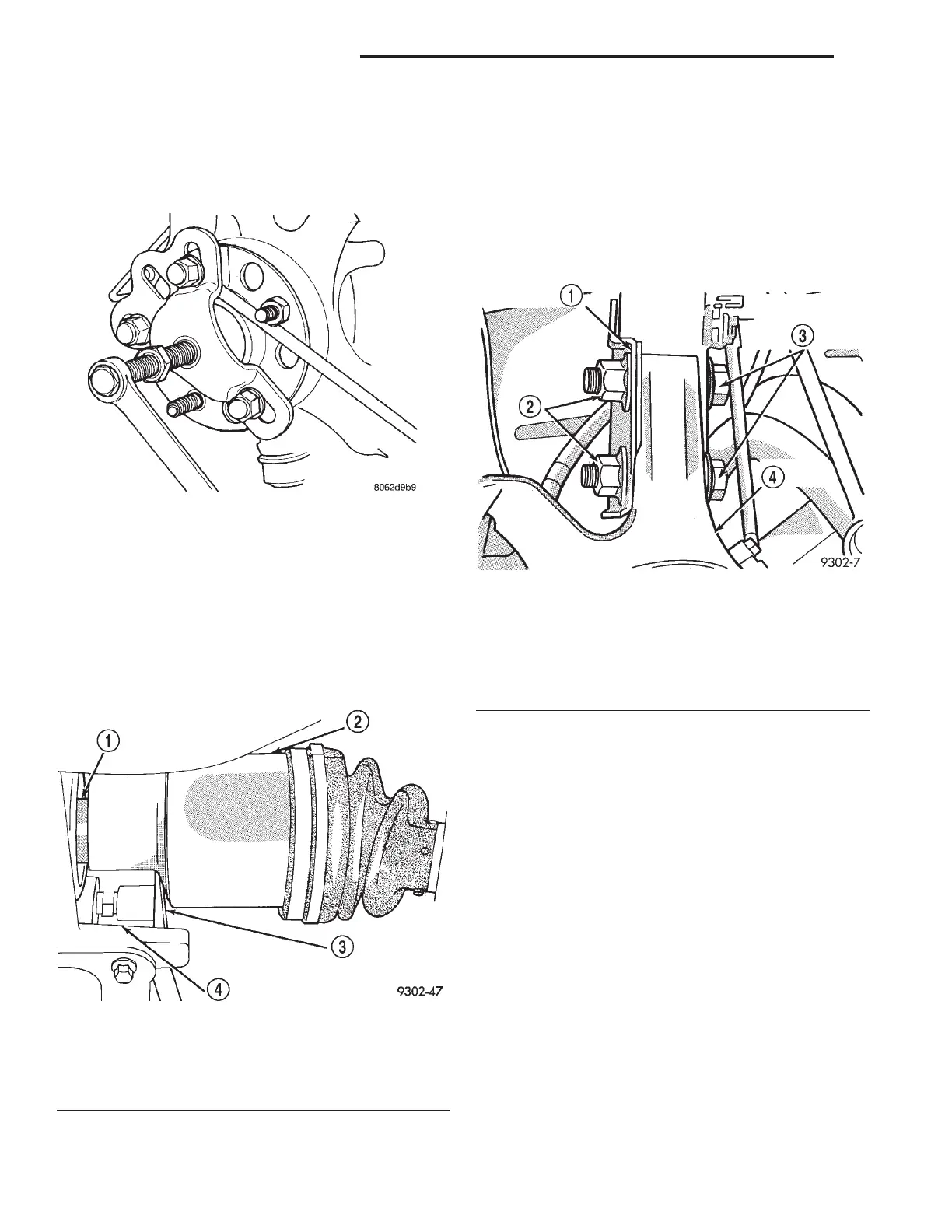
(9) Dislodge inner tripod joint from stub shaft
retaining snap ring on transaxle assembly (Fig. 9).
Inner tripod joint is dislodged from stub shaft retain-
ing snap ring, by inserting a pry bar between tran-
saxle case and inner tripod joint and prying on tripod
joint. Only disengage the inner tripod joint from
the retaining snap ring. Do not attempt to
remove the inner tripod joint from the trans-
mission stub shaft at this time.
CAUTION: The strut assembly to steering knuckle
bolts are serrated where they go through strut
assembly and steering knuckle. When removing
bolts, turn nuts off bolts. DO NOT TURN BOLTS IN
STEERING KNUCKLE. If bolts are turned, damage
to steering knuckle will result.
(10) Remove the strut assembly to steering
knuckle attaching bolts (Fig. 10).
(11) Remove the top of the steering knuckle from
the strut assembly.
CAUTION: When removing outer C/V joint from hub
and bearing assembly, do not allow the flinger disk
(Fig. 11) on hub and bearing assembly to become
damaged. Damage to the flinger disk will cause dirt
and water intrusion into bearing. Premature bearing
failure will result.
(12) Hold outer C/V joint assembly with one hand.
Grasp steering knuckle with other and rotate it out
and to the rear of the vehicle, until outer C/V joint
clears hub and bearing assembly (Fig. 11).
(13) Remove driveshaft inner tripod joint from
transaxle stub shaft. When removing driveshaft,
do not pull on interconnecting shaft to remove
inner tripod joint from stub shaft. Removal in
this manner will separate the spider assembly
from the tripod joint housing. Grasp inner tri-
pod joint (Fig. 12) and interconnecting shaft
and pull on both pieces at the same time.
Fig. 8 Removing Stub Axle From Hub/Bearing
Fig. 9 Inner Tripod Joint Removal From Stub Shaft
1 – TRANSMISSION STUB SHAFT
2 – INNER TRIPOD JOINT
3–PRYBAR
4 – TRANSAXLE
Fig. 10 Strut Assembly To Steering Knuckle
Attaching Bolts
1 – STRUT ASSEMBLY
2 – NUTS
3 – STRUT ASSEMBLY TO STEERING KNUCKLE ATTACHING
BOLTS
4 – STEERING KNUCKLE
3 - 6 DIFFERENTIAL AND DRIVELINE LH
REMOVAL AND INSTALLATION (Continued)