VALVE SPRINGS
DESCRIPTION
The valve springs are made from high strength,
chrome-silicon steel (Fig. 6). The springs are common
for intake and exhaust applications. The valve spring
seat is integral with the valve stem seal, which incor-
porates a garter spring to maintain consistent lubri-
cation control to the valve stem.
OPERATION
The valve spring returns the valve against its seat
for a positive seal of the combustion chamber.
TIMING DRIVE SYSTEM
DESCRIPTION
The timing drive system has been designed to pro-
vide quiet performance and reliability to support a
NON free-wheeling engine. The system consists of a
primary and secondary chain drive.
The primary timing chain drive (Fig. 7) uses a
single, double-flexure, inverted tooth type chain. The
primary chain drives both of the intake camshafts
directly from a sprocket mounted on the crankshaft.
In addition, the water pump is driven by the “back
side” of the primary chain, necessitating the double-
flexure type chain.
The chain is controlled by three fixed chain guides
and a pivoting tensioner arm (Fig. 7). These guides
utilize low-friction and long wearing nylon plastic
wear faces. To tension the primary chain, a fully
automatic spring-loaded, engine oil-fed, hydraulic
tensioner is used. The tensioner is mounted in the
right cylinder head with the plunger contacting the
pivoting tensioner arm. A mechanical ratchet mecha-
nism inside the tensioner prevents excessive chain
slack upon engine start-up as the chain wears. The
tensioner is designed with an internal oil reservoir to
assure noise-free performance, even during engine
start-up before oil pressure reaches the tensioner.
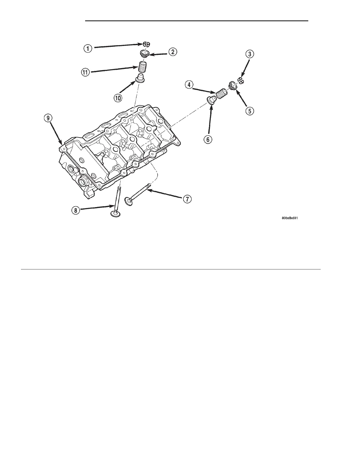
Fig. 6 Cylinder Head, Valves, and Springs
1 – VALVE KEEPER
2 – SPRING RETAINER
3 – VALVE KEEPER
4 – VALVE SPRING-EXHAUST
5 – SPRING RETAINER
6 – VALVE STEM SEAL
7 – VALVE-EXHAUST
8 – VALVE-INTAKE
9 – CYLINDER HEAD
10 – VALVE STEM SEAL
11 – VALVE SPRING-INTAKE
9 - 6 2.7L ENGINE LH
DESCRIPTION AND OPERATION (Continued)