DESCRIPTION
OPERATION
The driver side inflator assembly is mounted from
the back of the module housing. When supplied with
the proper electrical signal the inflator assembly will
produce a gas and discharge it directly into the cush-
ion. A protective cover is fitted to the front of the
Driver Airbag Module and forms a decorative cover
in the center of the steering wheel. This cover incor-
porates the integral horn switch. The driver airbag
module is mounted directly to the steering wheel.
IMPACT SENSOR
DESCRIPTION
The Airbag System is a supplemental safety device
designed to help protect the driver and passenger
from serious injury, caused by a frontal impact of the
vehicle.
The Occupant Restraint Controller’s (ORC) inter-
nal impact sensor provides verification of the direc-
tion and severity of an impact. The sensor is
mounted within the ORC.
OPERATION
The Occupant Restraint Controller (ORC) uses
data collected from it’s internal accelerometers to dis-
criminate the direction and severity of an impact.
The ORC will activate power stages internal to the
module in order to deploy the driver and passenger
side airbags once a predetermined threshold has
been exceeded. The ORC is calibrated for a particular
vehicle family and uses an advanced software algo-
rithm to discriminate the severity and direction of
any vehicle event.
PASSENGER AIRBAG MODULE
WARNING: NEVER DISASSEMBLE THE DRIVER/
PASSENGER AIRBAG MODULES, THERE ARE NO
SERVICEABLE PARTS WITHIN THE MODULES.
DESCRIPTION
The Passenger Airbag Module is located beneath
the instrument panel and pad assembly. The module
is mounted to a bracket (welded to the floor pan)
with three screws.
OPERATION
The passenger inflator assembly is within the mod-
ule housing. When supplied with the proper electrical
signal the inflator will produce a gas and discharge it
directly into the cushion. Upon deployment, the
instrument panel upper cover will tear open and
allow the passenger airbag to fully inflate.
DIAGNOSIS AND TESTING
AIRBAG SYSTEM TEST
(1) Open hood and disconnect the negative battery
cable remote terminal from the remote battery post
(Fig. 4).
(2) Connect the DRB lllt scan tool to the Data
Link connector, located on the left side of the steering
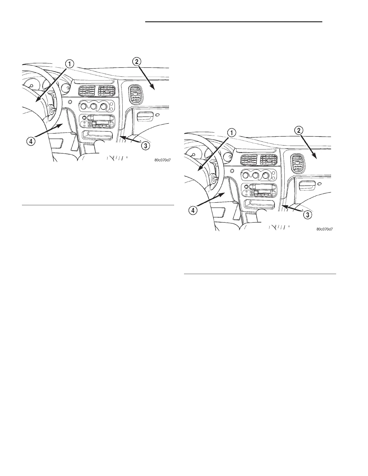
Fig. 2 Driver Airbag Location
1 – DRIVER AIRBAG MODULE
2 – PASSENGER AIRBAG MODULE
3 – OCCUPANT RESTRAINT CONTROLLER (ORC)
4 – KNEE BLOCKER
Fig. 3 Passenger Airbag Location
1 – DRIVER AIRBAG MODULE
2 – PASSENGER AIRBAG MODULE
3 – OCCUPANT RESTRAINT CONTROLLER (ORC)
4 – KNEE BLOCKER
8M - 2 PASSIVE RESTRAINT SYSTEMS LH
DESCRIPTION AND OPERATION (Continued)