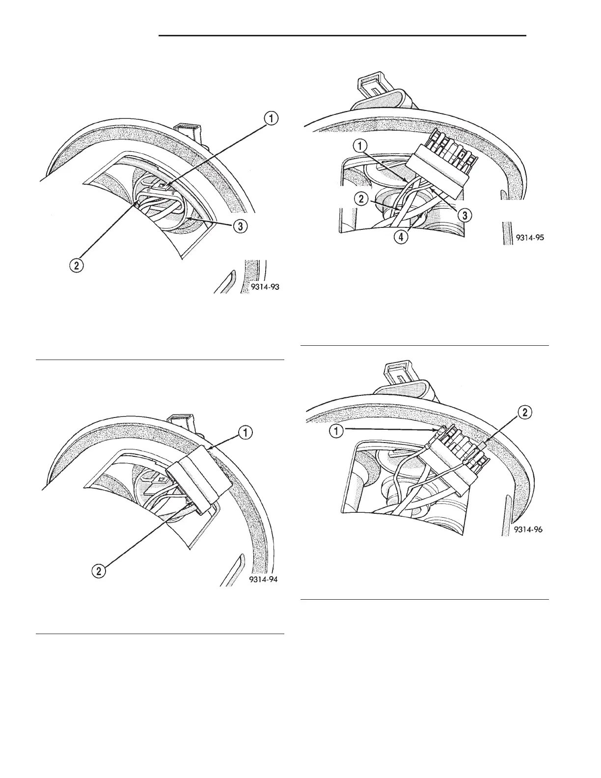
(1) Depress the retaining tab and remove the fuel
pump/level sensor connector from the bottom of the
fuel pump module electrical connector (Fig. 15).
(2) Remove wire terminal retaining clip from con-
nector (Fig. 16). Note the location of terminals for the
level sensor wires (Fig. 17).
(3) Using special tool 7812 or an equivalent, push
level sensor signal and ground terminals out of the
connector (Fig. 18).
(4) Insert a screwdriver between the fuel pump
module and the top of the level sensor housing (Fig.
19). Push level sensor down slightly.
(5) Slide level sensor wires through standpipe
inside fuel pump module (Fig. 20).
(6) Slide level sensor out of installation channel
(Fig. 19).
INSTALLATION
(1) Insert level sensor wires in bottom of stand-
pipe.
(2) Wrap wires into groove in back of level sensor
(Fig. 21).
Fig. 15 Fuel Pump/Level Sensor Connector
1–TAB
2 – FUEL PUMP/LEVEL SENSOR CONNECTOR
3 – BOTTOM OF FUEL PUMP MODULE ELECTRICAL
CONNECTOR
Fig. 16 Wire Terminal Retaining Clip
1 – WIRE TERMINAL RETAINING CLIP
2 – FUEL PUMP/LEVEL SENSOR CONNECTOR
Fig. 17 Wire Terminal Identification
1 – GRAY
(LEVEL SENSOR GROUND)
2 – BLACK
(FUEL PUMP –)
3 – BLUE
(LEVEL SENSOR SIGNAL)
4 – RED
(FUEL PUMP +)
Fig. 18 Level Sensor Signal and Ground Wires
1 – GRAY
(LEVEL SENSOR GROUND)
2 – BLUE
(LEVEL SENSOR SIGNAL)
14 - 12 FUEL SYSTEM LH
REMOVAL AND INSTALLATION (Continued)