CAUTION: Be sure the pressure test fittings being
installed into the proportioning valve, have the cor-
rect thread sizes for installation into the proportion-
ing valve and installation of the chassis brake
tubes.
(6) Correctly install Pressure Test Fittings, Special
Tool 6892–2 into the inlet port, and Special Tool
8187–2 into the outlet port, of the proportioning
valve (Fig. 16).
(7) Install the proportioning valve and the Pres-
sure Test Fittings, Special Tool 6892–2 and 8187–2,
as an assembly back into the chassis brake tube.
Connect Special Tool 6892–2 to the chassis brake
tube, and Special Tool 8187–2 to the brake flex hose.
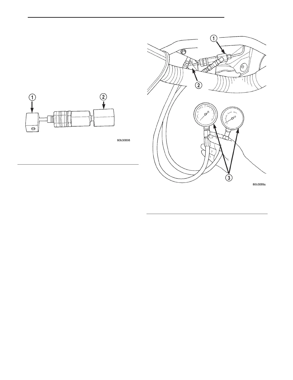
(8) Install a Pressure Gauge, Special Tool
C-4007-A into each pressure test fitting (Fig. 17).
Bleed any air out of the system. This includes bleed-
ing the air from the hose between the pressure test
fitting and pressure gauge, which is done at the pres-
sure gauge.
(9) With the aid of a helper, apply pressure to the
brake pedal until reading on proportioning valve
inlet gauge, is at the pressure shown on the following
chart. Then check the pressure reading on the pro-
portioning valve outlet gauge. If proportioning valve
outlet pressure does not agree with value shown on
the following chart, when inlet pressure shown on
chart is obtained, replace the proportioning valve. If
proportioning valve is within pressure specifications
do not replace proportioning valve.
(10) Remove the pressure gauges from the pres-
sure test fittings.
(11) Remove the proportioning valve and the Pres-
sure Test Fittings, Special Tool 6892–2, and 8187–2
from the chassis brake tube and rear flex hose.
Remove the pressure test fittings from the propor-
tioning valve (Fig. 16).
(12) Install the rear brake flex hose to its mount-
ing bracket using a new retainer clip.
(13) Install the proportioning valve to the rear
brake flex hose. Tighten to a torque of 17 N·m (145
in. lbs.).
(14) Install the chassis brake tube to the propor-
tioning valve (Fig. 15). Tighten the tube nut to a
torque of 17 N·m (145 in. lbs.).
(15) Bleed the affected brake line. See Bleeding
Brake System in the Service Adjustments section of
the manual for proper bleeding procedure.
(16) On vehicles with Antilock Brakes, repeat the
above steps for the other proportioning valve.
(17) If no problem is found with the proportioning
valves, check the rear wheel brake shoe linings for
contamination or for replacement brake shoes not
meeting OEM brake lining material specifications.
These conditions can also be a possible cause for a
premature rear wheel skid.
Fig. 16 Proportioning Valve With Fittings
1 – SPECIAL TOOL 8187–2
2 – SPECIAL TOOL 6892–2
Fig. 17 Pressure Gauges Installed
1 – SPECIAL TOOL 6892–2
2 – SPECIAL TOOL 8187–2
3 – SPECIAL TOOL C-4007–A
LH BRAKES 5 - 15
DIAGNOSIS AND TESTING (Continued)