(8) Install upper side rail first and then the lower
side rail.
(9) Install No. 2 piston ring and then No. 1 piston
ring (Fig. 24).
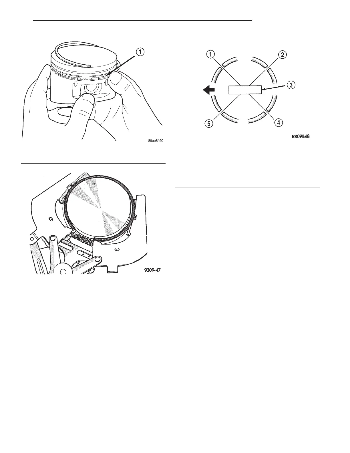
(10) Position piston ring end gaps as shown in
(Fig. 25).
(11) Position oil ring expander gap at least 45°
from the side rail gaps but not on the piston pin cen-
ter or on the thrust direction. Staggering ring gap is
important for oil control.
CONNECTING ROD BEARING—INSTALLATION
Fit all rods on one bank until complete.
The bearing caps are not interchangeable and
should be marked at removal to insure correct
assembly.
CAUTION: Care must be taken not to damage the
fractured rod and cap joint face surfaces as engine
damage may occur.
The bearing shells must be installed with the
tangs inserted into the machined grooves in the rods
and caps. Also, assure that the hole in upper bearing
half aligns with oil squirt hole in rod. Install cap
with the tangs on the same side as the rod.
CAUTION: Assure that hole in upper bearing half
aligns with hole in connecting rod as engine dam-
age may occur.
Limits of taper or out-of-round on any crankshaft
journals should be held to 0.015 mm (0.0006 in.).
Bearings are available 0.025 mm (0.001 in.) and
0.250 mm (0.010 in.) undersize. Install the bear-
ings in pairs. Do not use a new bearing half
with an old bearing half. Do not file the rods or
bearing caps.
(1) Follow procedure specified in the Standard Ser-
vice Procedure Section for Selecting and Measuring
Main Bearing Clearance and Connecting Rod Bear-
ing Clearance (Fig. 26). Refer to Engine Specifica-
tions.
NOTE: The connecting rod bearing cap bolts must
be examined before reuse. If the threads are necked
down the bolts should be replaced (Fig. 27).
NOTE: Connecting rod bolts are retained in the rod
cap with a light press fit. If bolts are to be removed,
use a hammer and punch to drive bolts from con-
necting rod cap using care not to damage fractured
cap surface.
Fig. 23 Side Rail—Installation
1 – SIDE RAIL END
Fig. 24 Upper and Intermediate Rings—Installation
Fig. 25 Piston Ring End Gap Position
1 – SIDE RAIL UPPER
2 – NO. 1 RING GAP
3 – PISTON PIN
4 – SIDE RAIL LOWER
5 – NO. 2 RING GAP AND SPACER EXPANDER GAP
LH 2.7L ENGINE 9 - 25
SERVICE PROCEDURES (Continued)