INSTALLATION
(1) Position isolator onto crossmember.
(2) Install bolts attaching isolator to crossmember
and tighten to 33 N·m (250 in. lbs.) (Fig. 39).
(3) Lower transaxle onto isolator.
(4) Install isolator nuts and tighten to 61 N·m (45
ft. lbs.) (Fig. 39).
(5) Lower vehicle.
STRUCTURAL COLLAR
REMOVAL
(1) Raise vehicle on hoist.
(2) Remove bolts attaching structural collar to oil
pan and transmission housing (Fig. 40).
(3) Remove collar (Fig. 40).
INSTALLATION
CAUTION: The collar must be tighten using this
service procedure, as damage to collar and/or oil
pan may occur.
(1) Install structural collar (Fig. 40) using the fol-
lowing tightening sequence:
a. Install the vertical collar to oil pan bolts.
Torque bolts initially to 1.1 N·m (10 in. lbs.).
b. Install the horizontal collar to transmission
bolts and torque to 55 N·m (40 ft. lbs.).
c. Starting with the center vertical bolts and work-
ing outward, final torque bolts to 55 N·m (40 ft. lbs.).
(2) Lower vehicle.
ENGINE ASSEMBLY
REMOVAL
(1) Release fuel pressure. Refer to FUEL SYSTEM
for procedure.
(2) Disconnect negative cable at remote jumper
terminal located at right strut tower (Fig. 41).
(3) Mark hood position at hinges and remove hood.
(4) Drain cooling system. Refer to COOLING SYS-
TEM for procedure.
(5) Remove both wiper arms.
(6) Remove right and left cowl covers (Fig. 42).
(7) Remove cowl support (Fig. 43).
(8) Remove air cleaner assembly and air inlet hose
(Fig. 44).
(9) Remove upper radiator crossmember. Refer to
BODY for procedure.
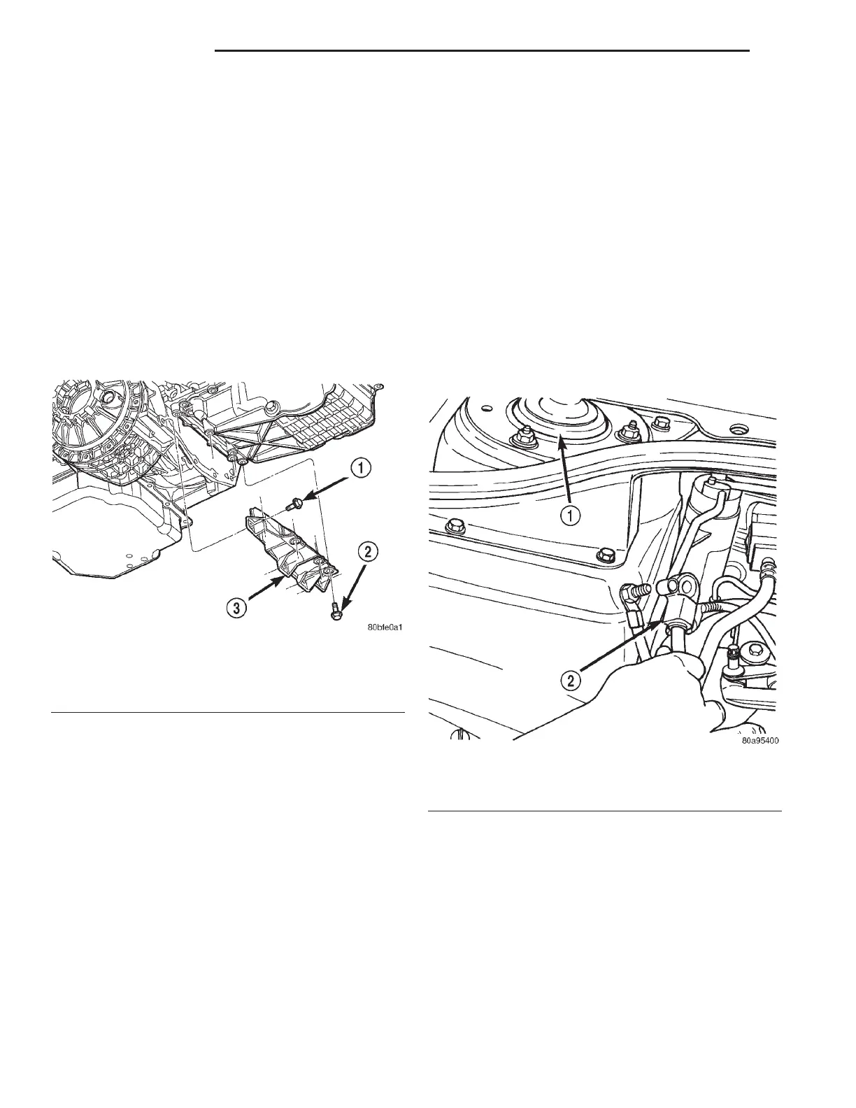
Fig. 40 Structural Collar
1 – BOLT-HORIZONTAL
2 – BOLT-VERTICAL
3 – STRUCTURAL COLLAR
Fig. 41 Negative Cable Remote Terminal
1 – RIGHT STRUT TOWER
2 – BATTERY NEGATIVE CABLE
9 - 32 2.7L ENGINE LH
REMOVAL AND INSTALLATION (Continued)