STARTER RELAY
WARNING: CHECK TO ENSURE THAT THE TRANS-
MISSION IS IN THE PARK/NEUTRAL POSITION
WITH THE PARKING BRAKE APPLIED.
RELAY TEST
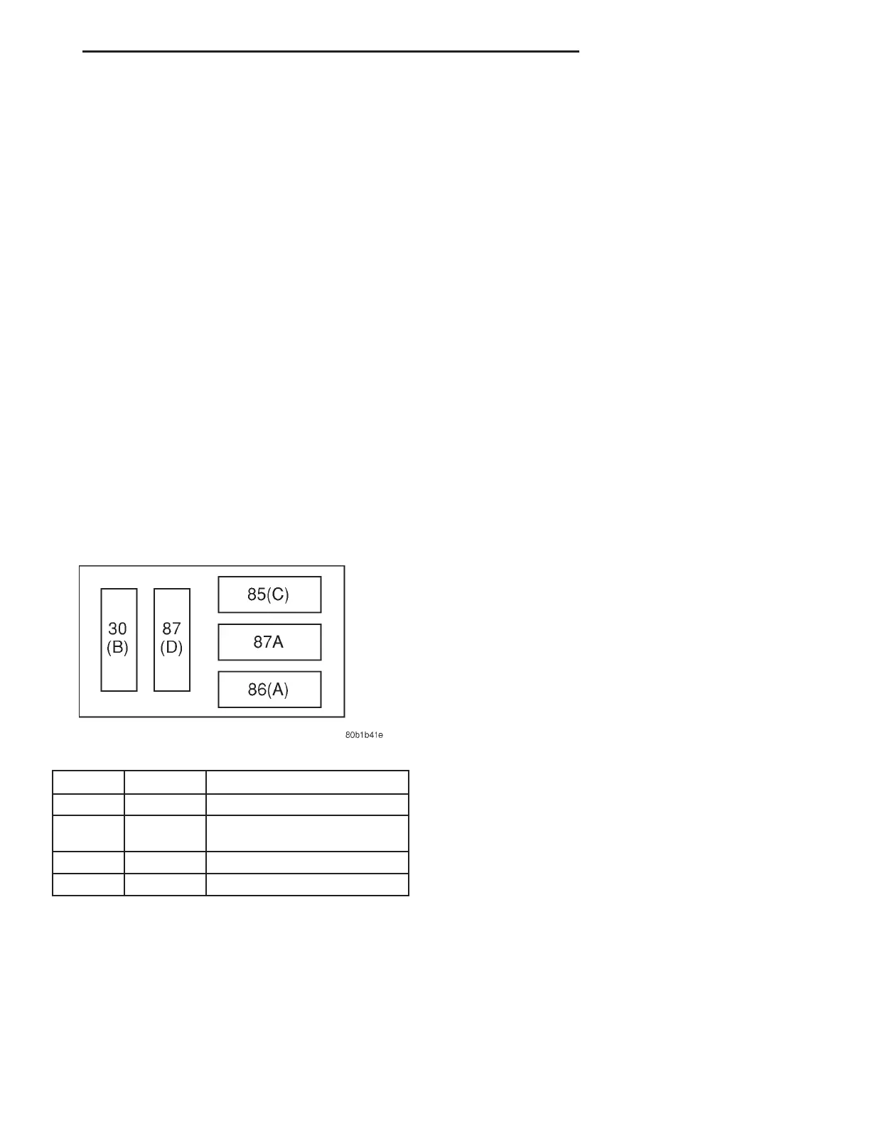
The starter relay is located in the Power Distribu-
tion Center (PDC) in the engine compartment. Refer
to the PDC label for relay identification and location.
Remove the starter relay from the PDC as
described in this group to perform the following tests:
(1) A relay in the de-energized position should
have continuity between terminals 87A and 30, and
no continuity between terminals 87 and 30. If OK, go
to Step 2. If not OK, replace the faulty relay.
(2) Resistance between terminals 85 and 86 (elec-
tromagnet) should be 75 65 ohms. If OK, go to Step
3. If not OK, replace the faulty relay.
(3) Connect a battery B+ lead to terminals 86 and
a ground lead to terminal 85 to energize the relay.
The relay should click. Also test for continuity
between terminals 30 and 87, and no continuity
between terminals 87A and 30. If OK, refer to Relay
Circuit Test procedure. If not OK, replace the faulty
relay.
RELAY CIRCUIT TEST
(1) The relay common feed terminal cavity (30) is
connected to battery voltage and should be hot at all
times. If OK, go to Step 2. If not OK, repair the open
circuit to the PDC fuse as required.
(2) The relay normally closed terminal (87A) is
connected to terminal 30 in the de-energized position,
but is not used for this application. Go to Step 3.
(3) The relay normally open terminal (87) is con-
nected to the common feed terminal (30) in the ener-
gized position. This terminal supplies battery voltage
to the starter solenoid field coils. There should be
continuity between the cavity for relay terminal 87
and the starter solenoid terminal at all times. If OK,
go to Step 4. If not OK, repair the open circuit to the
starter solenoid as required.
(4) The coil battery terminal (86) is connected to
the electromagnet in the relay. It is energized when
the ignition switch is held in the Start position.
Check for battery voltage at the cavity for relay ter-
minal 86 with the ignition switch in the Start posi-
tion, and no voltage when the ignition switch is
released to the On position. If OK, go to Step 5. If
not OK, check for an open or short circuit to the igni-
tion switch and repair, if required. If the circuit to
the ignition switch is OK, see the Ignition Switch
Test procedure in this group.
(5) The coil ground terminal (85) is connected to
the electromagnet in the relay. It is grounded
through the transmission range sensor only when the
gearshift selector lever is in the Park or Neutral
positions. Check for continuity to ground at the cav-
ity for relay terminal 85. If not OK with an auto-
matic transmission, check for an open or short circuit
to the transmission range sensor and repair.
SAFETY SWITCHES
For diagnostics of the Transmission Range Sensor,
refer to Group 21, Transaxle.
IGNITION SWITCH
After testing starter solenoid and relay, test igni-
tion switch and wiring. Refer to Group 8D, Ignition
Systems or Group 8W, Wiring Diagrams. Check all
wiring for opens or shorts, and all connectors for
being loose or corroded.
BATTERY
For battery diagnosis and testing, refer to Group
8A, Battery for procedures.
ALL RELATED WIRING AND CONNECTORS
Refer to Group 8W, Wiring Diagrams.
FEED CIRCUIT RESISTANCE TEST
Before proceeding with this operation, review Diag-
nostic Preparation and Starter Feed Circuit Tests.
The following operation will require a voltmeter,
accurate to 1/10 of a volt.
CAUTION: Ignition and Fuel systems must be dis-
abled to prevent engine start while performing the
following tests.
Starter Relay Pinout
CAV COLOR FUNCTION
30 (B) RD B (+)
85 (C) TN P/N POSITION SW. SENSE
(AUTO)
86 (A) YL IGNITION SWITCH OUTPUT
87 (D) LG STARTER RELAY OUTPUT
LH STARTING SYSTEMS 8B - 3
DIAGNOSIS AND TESTING (Continued)