(4) Install outer C/V joint seal boot retaining
clamp, onto interconnecting shaft. Install replace-
ment outer C/V joint sealing boot onto interconnect-
ing shaft. Outer C/V joint seal boot MUST be
positioned on interconnecting shaft, so only the
thinnest (sight) groove on interconnecting shaft
is visible (Fig. 35).
(5) Clamp sealing boot on interconnecting shaft
using Crimper, Special Tool C-4975 and the following
procedure. Place crimping tool C-4975 over bridge of
clamp (Fig. 36). Tighten nut on crimping tool C-4975
until jaws on tool are closed completely together, face
to face (Fig. 37).
CAUTION: Seal must not be dimpled, stretched or
out of shape in any way. If seal is NOT shaped cor-
rectly, equalize pressure in seal and shape it by
hand.
(6) Position outer C/V joint seal boot, into boot
retaining groove on outer C/V joint housing. Install
seal boot to outer C/V joint retaining clamp evenly on
sealing boot.
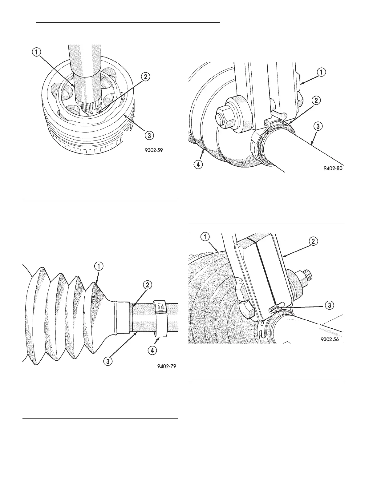
Fig. 34 Outer C/V Joint Installed On Interconnecting
Shaft
1 – INTERCONNECTING SHAFT
2 – RETAINING SNAP RING
3 – OUTER C/V JOINT ASSEMBLY
Fig. 35 Seal Boot Correctly Positioned On
Interconnecting Shaft
1 – SEALING BOOT
2 – INTERCONNECTING SHAFT THINNEST GROOVE
3 – INTERCONNECTING SHAFT
4 – BOOT CLAMP
Fig. 36 Crimping Tool Installed On Sealing Boot
Clamp
1 – SPECIAL TOOL C-4975
2 – SEALING BOOT CLAMP
3 – INTERCONNECTING SHAFT
4 – SEALING BOOT
Fig. 37 Sealing Boot Retaining Clamp Installed
1 – SEALING BOOT
2 – SPECIAL TOOL C-4975
3 – CLAMP BRIDGE
LH DIFFERENTIAL AND DRIVELINE 3 - 15
DISASSEMBLY AND ASSEMBLY (Continued)