(7) Clamp sealing boot onto outer C/V joint hous-
ing using Crimper, Special Tool C-4975 and the fol-
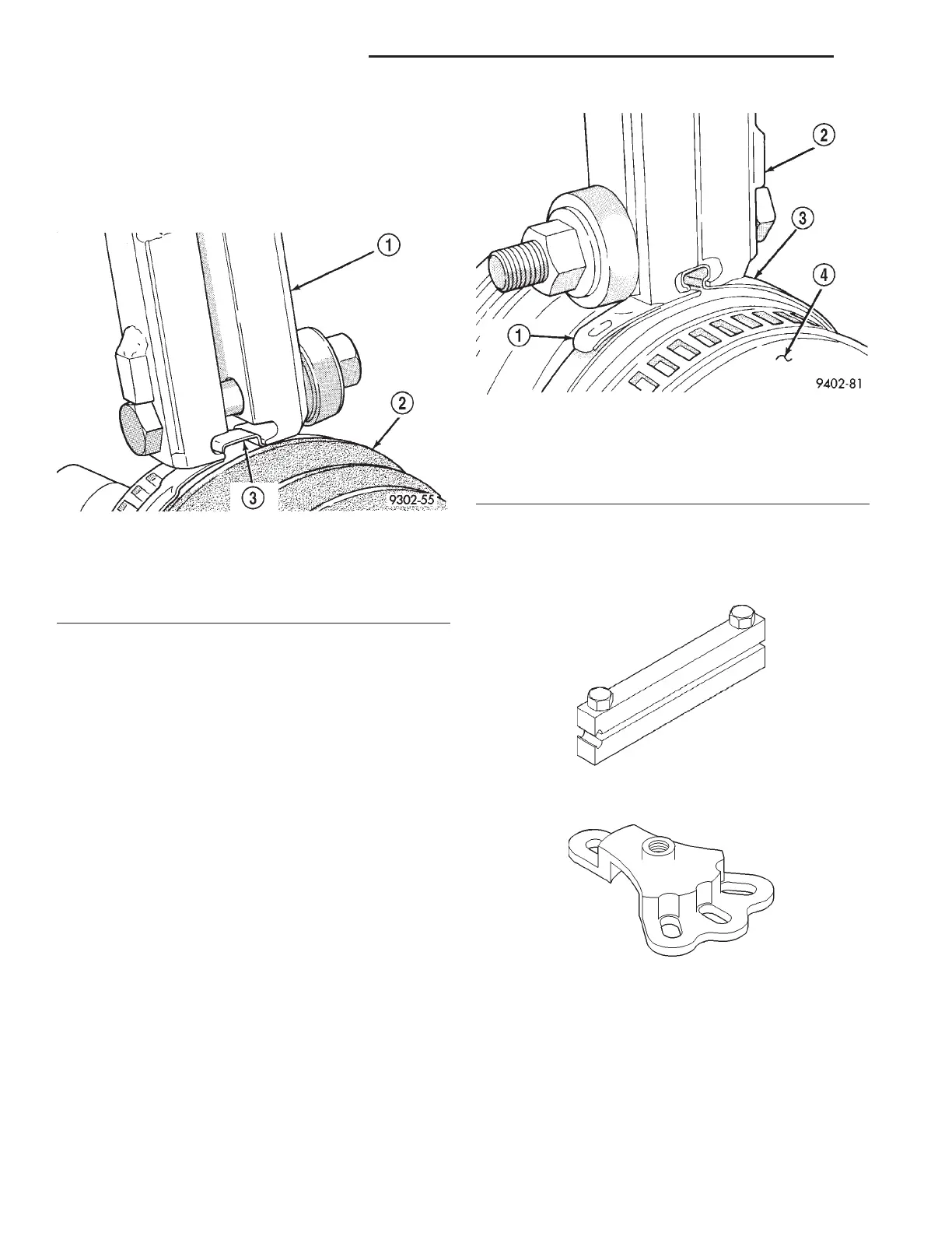
lowing procedure. Place crimping tool C- 4975 over
bridge of clamp (Fig. 38). Tighten nut on crimping
tool C-4975 until jaws on tool are closed completely
together, face to face (Fig. 39).
(8) Install the driveshaft requiring boot replace-
ment back on the vehicle. See “Driveshaft Removal
and Installation” in this section of the service man-
ual for the required driveshaft installation procedure.
SPECIFICATIONS
TORQUE SPECIFICATIONS
DESCRIPTION TORQUE
Caliper To Knuckle Bolts .... 19N·m(168 in. lbs.)
Driveshaft Nut ........... 150N·m(105 ft. lbs.)
Front Wheel Lug Nuts...... 135N·m(100 ft. lbs.)
Knuckle To Strut Bolt Nuts . . 169 N·m (125 ft. lbs.)
Tie Rod End To Knuckle ...... 61N·m(45ft.lbs.)
SPECIAL TOOLS
DRIVESHAFT
Fig. 38 Crimping Tool Installed On Sealing Boot
Clamp
1 – SPECIAL TOOL C-4975
2 – SEALING BOOT
3 – CLAMP BRIDGE
Fig. 39 Sealing Boot Retaining Clamp Installed
1 – BOOT CLAMP
2 – SPECIAL TOOL C-4975
3 – SEALING BOOT
4 – OUTER C/V JOINT
Boot Clamp Installer C-4975A
Puller 6790
3 - 16 DIFFERENTIAL AND DRIVELINE LH
DISASSEMBLY AND ASSEMBLY (Continued)