(10) Remove dial indicator and install spark plug.
(11) Remove camshaft alignment Special Tools
6642 and install cam covers and O-rings. Tighten fas-
teners to 28 N·m (250 in. lbs.).
(12) Install timing belt covers. Refer to Timing
Belt Covers in this section.
(13) Install crankshaft damper.
(14) Install accessory drive belts. Refer to COOL-
ING SYSTEM for procedure.
(15) Fill cooling system. Refer to COOLING SYS-
TEM for procedure.
(16) Start engine and allow to idle for approxi-
mately 1 minute. If a noticeable noise is present from
the timing belt/tensioner, air has possibly entered the
tensioner.
(a) To remove air from tensioner; using a DRB
IIIt, operate the engine at speed of 1600–2000
RPM for 10 minutes. This will purge air from ten-
sioner and noise will be dissipated.
NOTE: If air is present, the tensioner will be soft
and may generate noise. This noise should disap-
pear after no more than 15 minutes of engine run-
ning time.
ROCKER ARMS AND SHAFT ASSEMBLY
CAUTION: The rocker arm shafts are hollow and
are used as lubrication oil passages. The rocker
arm and shaft assembly on the RIGHT side of the
engine has an oil passage hole from the cylinder
head to the third rocker shaft support. The rocker
arm shaft assembly on the LEFT side of the engine
has an oil passage hole from the cylinder head to
the second rocker shaft support.
REMOVAL
(1) Remove cylinder head covers. Refer to proce-
dure in this section.
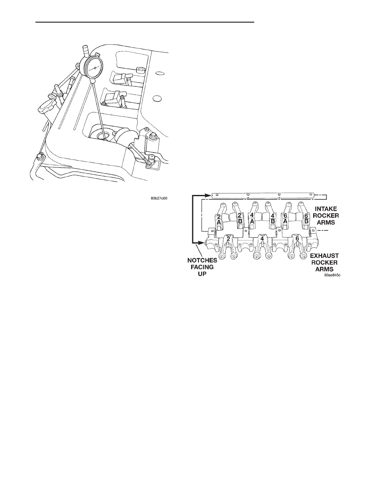
(2) Identify the rocker arm assembly and rocker
arms before disassembly (Fig. 80).
(3) Remove rocker arm assembly bolts.
(4) Remove rocker arm assembly.
NOTE: To prevent air ingestion into lash adjusters,
avoid turning rocker arm assembly upside down.
CAUTION: Do not allow rocker arm assembly to
rest on lash adjusters, as damage may occur to
lash adjusters and/or plastic retainers.
DISASSEMBLY
(1) Remove dowel pin usinga4mmscrew, nut,
spacer, and washer installed into the pin (Fig. 81).
Tighten the screw into the pin, then loosen the nut
on the screw. This will pull the dowel out of the shaft
support. Do not reuse dowel pins. Remove the rocker
arms and pedestals in order.
(2) Check the rocker arm mounting portion of the
shafts for wear or damage. Replace if damaged or
heavily worn.
(3) Check shaft oil holes for clogging with small
wire, clean as required.
ASSEMBLY
CAUTION: New dowel pins must be installed during
assembly.
(1) Install the rocker arms, and pedestals onto the
shaft.
Fig. 79 Dial Indicator Locating Piston at TDC
Fig. 80 Rocker Arms and Shaft Identification—Left
Bank
LH 3.2/3.5L ENGINE 9 - 119
REMOVAL AND INSTALLATION (Continued)

 Loading...


