DISASSEMBLY AND ASSEMBLY
OIL PUMP
DISASSEMBLY
(1) To remove the relief valve, proceed as follows:
(2) Remove cotter pin. Drill a 3.175 mm (1/8 inch.)
hole into the relief valve retainer cap and insert a
self-threading sheet metal screw into cap.
(3) Clamp screw into a vise and while supporting
oil pump body, remove cap by tapping oil pump body
using a soft hammer. Discard retainer cap and
remove spring and relief valve (Fig. 130).
(4) Remove oil pump cover screws, and lift off
cover.
(5) Remove pump rotors.
(6) Wash all parts in a suitable solvent and inspect
carefully for damage or wear (Fig. 131).
ROCKER ARMS AND SHAFT ASSEMBLY
DISASSEMBLY
(1) Remove dowel pin usinga4mmscrew, nut,
spacer, and washer installed into the pin (Fig. 132).
Thread the screw into the pin, then loosen the nut on
the screw. This will pull the dowel out of the shaft
support. Do not reuse dowel pins. Remove the rocker
arms and pedestals in order.
(2) Check the rocker arm mounting portion of the
shafts for wear or damage. Replace if damaged or
heavily worn.
(3) Check shaft oil holes for clogging with small
wire, clean as required.
ASSEMBLY
CAUTION: New dowel pins must be installed when
reassembling.
(1) Install the rocker arms, and pedestals onto the
shaft.
(2) Install dowel pins (Fig. 133). Dowel pins pass
through the pedestal into the exhaust rocker shafts.
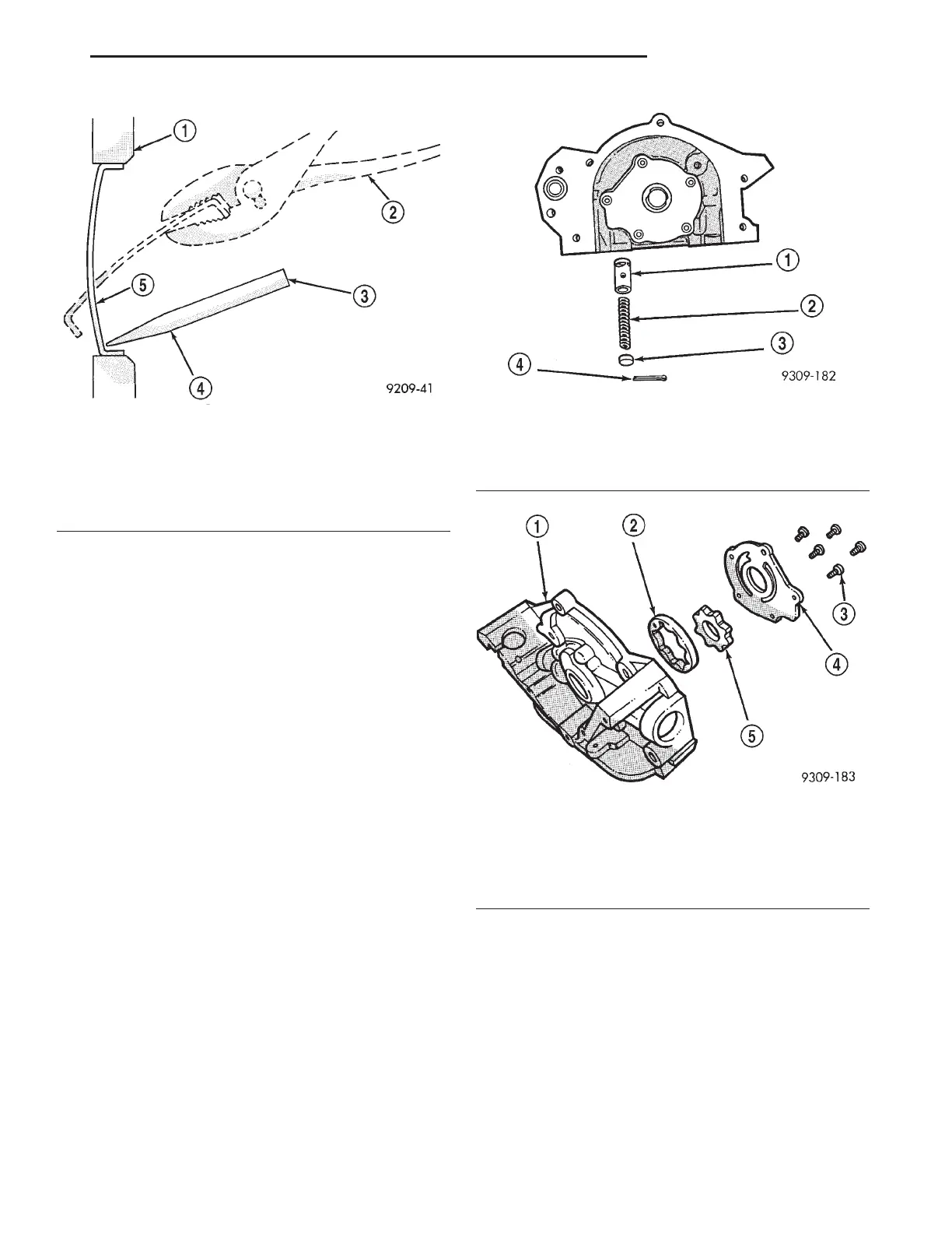
Fig. 129 Core Hole Plug Removal
1 – CYLINDER BLOCK
2 – REMOVE PLUG WITH PLIERS
3 – STRIKE HERE WITH HAMMER
4 – DRIFT PUNCH
5 – CUP PLUG
Fig. 130 Oil Pressure Relief Valve
1 – RELIEF VALVE
2 – SPRING
3 – RETAINER CAP
4 – COTTER PIN
Fig. 131 Oil Pump
1 – OIL PUMP BODY
2 – OIL PUMP OUTER ROTOR
3 – SCREWS
4 – OIL PUMP COVER
5 – OIL PUMP INNER ROTOR
LH 3.2/3.5L ENGINE 9 - 137
REMOVAL AND INSTALLATION (Continued)