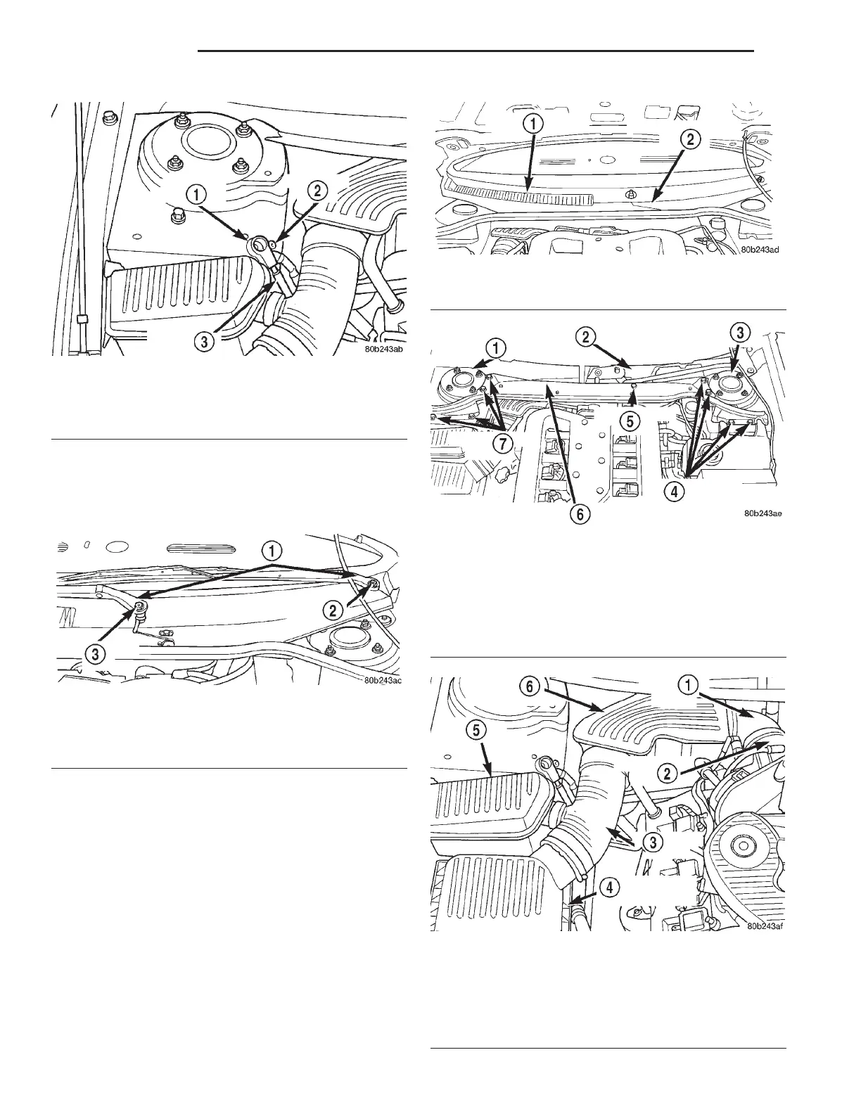
(4) Remove caps from both wiper arms at the
attachment to the pivots to expose the wiper arm
attaching nuts. Remove the nut (Fig. 11) attaching
each wiper arm to its pivot
(5) Remove the wiper arms from the pivots. Wiper
arms are removed from the pivots by rocking them
back and force on the pivots until they can be pulled
off the pivots.
(6) Remove the wiper module cover and cowl cover
(Fig. 12).
(7) Remove the 8 bolts, attaching the reinforce-
ment (Fig. 13) to the strut towers and the 1 bolt (Fig.
13) attaching the wiper module to the reinforcement.
Remove the reinforcement from the vehicle.
(8) Remove the in-line resonator and inlet hose
(Fig. 14) from the throttle body and air let hose com-
ing from the lid of the air cleaner housing.
NOTE: When locking the steering wheel, the front
tires of the vehicle are to be facing straight ahead.
Fig. 10 Correctly Isolated Remote Ground Cable
1 – CABLE ISOLATOR
2 – GROUND STUD
3 – GROUND CABLE
Fig. 11 Wiper Arm Attachment To Pivot
1 – WIPER ARMS
2 – ATTACHING NUT
3 – ATTACHING NUT
Fig. 12 Wiper Module And Cowl Cover
1 – COWL COVER
2 – WIPER MODULE COVER
Fig. 13 Reinforcement Attachment To Vehicle
1 – RIGHT STRUT TOWER
2 – WIPER MODULE
3 – LEFT STRUT TOWER
4 – ATTACHING BOLTS
5 – ATTACHING BOLT
6 – REINFORCEMENT
7 – ATTACHING BOLTS
Fig. 14 In-Line Resonator And Air Inlet Hose
1 – AIR INLET HOSE
2 – THROTTLE BODY
3 – AIR INLET HOSE
4 – AIR CLEANER HOUSING LID
5 – RESONATOR
6 – IN-LINE RESONATOR
19 - 12 STEERING LH
REMOVAL AND INSTALLATION (Continued)

 Loading...


