(5) Disconnect electrical connectors and vacuum
hose.
(6) Remove two nuts attaching speed control cable
and mounting bracket to servo.
(7) Pull cable away from servo to expose retaining
clip and remove clip attaching cable to servo.
(8) Remove servo mounting bracket.
INSTALLATION
(1) Slide cable into throttle cable bracket and
engage retaining tabs.
(2) Rotate the throttle cam forward to the wide
open position and install speed control cable clasp
(Fig. 2).
(3) Rotate the throttle cam forward to the wide
open position and install throttle cable clasp.
(4) Install retaining clip to cable at servo.
(5) Insert servo studs through holes in the mount-
ing bracket and speed control cable.
(6) Install nuts, tighten to 6.7 N·m (60 in. lbs.).
(7) Connect vacuum hose to servo.
(8) Connect electrical connector.
(9) Install servo and bracket and tighten nuts and
bolt.
(10) Connect negative battery cable.
SPEED CONTROL SERVO CABLE—3.2/3.5L
REMOVAL
(1) Disconnect the negative battery cable.
(2) Remove throttle cable bracket from intake
manifold.
(3) Remove speed control cable from throttle cam
by sliding clasp out hole used for throttle cable.
(4) Remove the throttle cable (with retaining tab)
and then slide cable speed control cable out from
bracket.
(5) Remove one bolt and two nuts from servo
bracket.
(6) Disconnect electrical connectors and vacuum
hose.
(7) Remove two nuts attaching mounting bracket
and speed control cable to servo.
(8) Pull cable away from servo to expose retaining
clip and remove clip attaching cable to servo.
(9) Remove servo mounting bracket.
INSTALLATION
(1) Slide speed control cable into bracket and with
locator positioned into notch in bracket, then slide
throttle cable into bracket and engage retaining tab.
(2) Rotate the throttle cam forward to the wide
open position and install speed control cable clasp
(Fig. 2).
(3) Rotate the throttle cam forward to the wide
open position and install throttle cable clasp.
(4) Install throttle cable bracket and tighten bolts.
(5) Route cable through bracket and install retain-
ing clip to cable at servo.
(6) Insert servo studs through holes in mounting
bracket and speed control cable.
(7) Install nuts, tighten to 6.7 N·m (60 in. lbs.).
(8) Connect vacuum hose to servo.
(9) Connect electrical connector.
(10) Install servo and bracket and tighten bolts.
(11) Connect negative battery cable.
VACUUM RESERVOIR
REMOVAL
(1) Disconnect the negative battery cable.
(2) Remove the Powertrain Control Module (PCM)
refer to the Fuel Injection System section.
(3) Remove and reposition coolant reservoir.
(4) Remove PDC and bracket.
(5) Remove vacuum reservoir.
(6) Disconnect vacuum hose
INSTALLATION
(1) Connect vacuum hose.
(2) Install vacuum reservoir and tighten fasteners.
(3) Install PDC and bracket and tighten fasteners.
(4) Install coolant reservoir.
(5) Install PCM refer to the Fuel Injection System
section.
(6) Connect the negative battery cable.
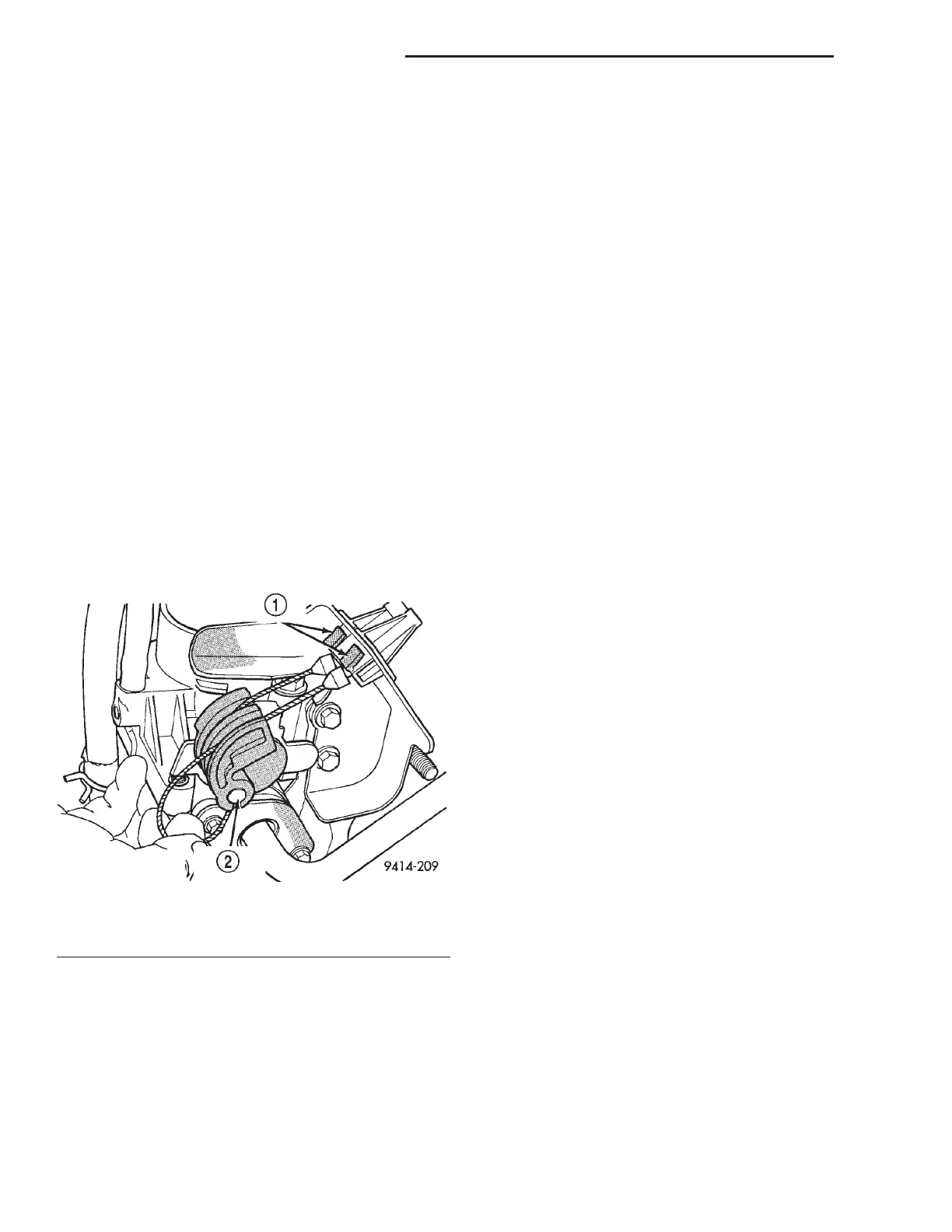
Fig. 2 Disconnecting Throttle Cable—Typical
1–TABS
2 – CABLE CLASP
8H - 6 VEHICLE SPEED CONTROL SYSTEM LH
REMOVAL AND INSTALLATION (Continued)