WARNING: DISCONNECT AND ISOLATE THE NEG-
ATIVE BATTERY CABLE REMOTE TERMINAL
BEFORE BEGINNING ANY FRONT SEAT REMOVAL
OR INSTALLATION PROCEDURE. THIS WILL DIS-
ABLE THE AIRBAG SYSTEM. FAILURE TO DISCON-
NECT THE BATTERY COULD RESULT IN
ACCIDENTAL AIRBAG DEPLOYMENT AND POSSI-
BLE PERSONAL INJURY.
WARNING: ONCE THE NEGATIVE CABLE IS DIS-
CONNECTED WAIT FOR 2 MINUTES BEFORE
REMOVING ANY AIRBAG SYSTEM COMPONENTS.
REMOVAL - NONDEPLOYED
(1) Position the right front seat in its full forward
position.
(2) Disconnect and isolate the negative battery
cable.
(3) Remove plastic back panel from seat back (Fig.
18). Refer to Group 23, Body for a detailed procedure.
(4) Disengage seat back trim cover J-strap from
the upper, lower and airbag side of seat back.
(5) Disconnect the side airbag module electrical
connector (Fig. 19). Slide yellow locking tab down to
unlock. Then with two fingers, push two side retain-
ing tabs in and pull connector straight from module.
(6) Remove the side airbag module retaining nuts
(Fig. 20).
(7)
Grasp the upper airbag side of the trim cover and
pull trim cover and cushion over top of seat back frame
(Fig. 20). This will allow room to remove side airbag
module without damaging trim cover or cushion.
(8) Working between seat back trim cover/cushion
and frame unhook airbag module studs from nylon
sleeve and slide module out of sleeve. Be careful not
to tear nylon sleeve as this will affect function of air-
bag system.
CAUTION: BE CERTAIN NOT TO TEAR AIRBAG
NYLON SLEEVE DURING THE REMOVAL PROCE-
DURE. IF THIS OCCURS THE SEAT BACK TRIM
COVER MUST BE REPLACED.
INSTALLATION - NONDEPLOYED
CAUTION: DO NOT REPLACE A DEPLOYED AIR-
BAG. IF SEAT AIRBAG HAS BEEN DEPLOYED ALL
DAMAGED PARTS MUST BE REPLACED.
NOTE: AIRBAG CONNECTOR MUST FACE DOWN
(TOWARD SEAT CUSHION) AFTER INSTALLATION.
(1) Carefully slide the seat airbag module in nylon
sleeve until mounting studs line up with holes pro-
vided in nylon sleeve. Be careful not to tear nylon
sleeve as this will affect function of airbag system.
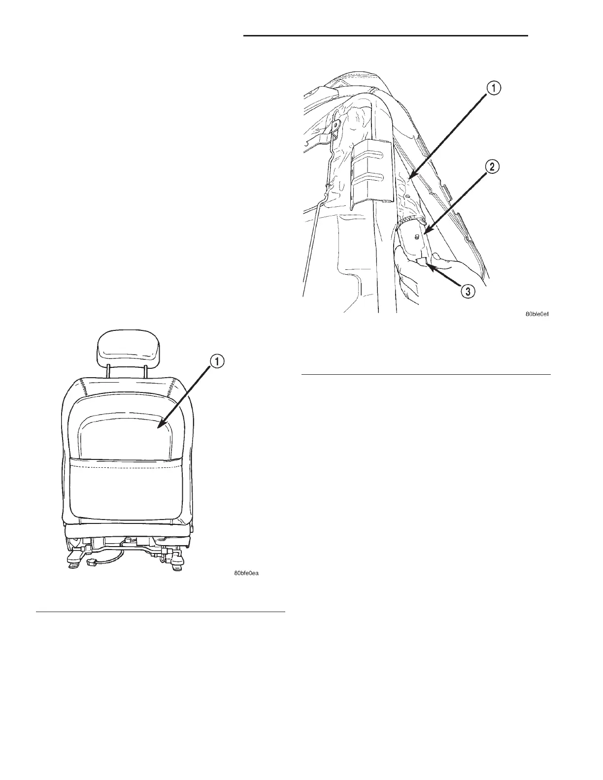
Fig. 18 Front Seat Back Panel
1 – FRONT SEAT BACK PANEL
Fig. 19 Seat Airbag Electrical Connector
1 – AIRBAG MODULE NYLON SLEEVE
2 – AIRBAG MODULE
3 – AIRBAG MODULE ELECTRICAL CONNECTOR
8M - 16 PASSIVE RESTRAINT SYSTEMS LH
REMOVAL AND INSTALLATION (Continued)
2000 LHS, 300M, CONCORDE AND INTREPID