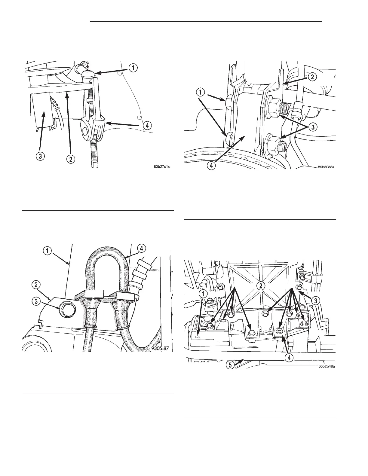
Puller, Special Tool C-3894A (Fig. 46), then remove
nut and tie rod from the steering arm.
(7) If vehicle is equipped with antilock brakes,
remove the speed sensor cable routing bracket from
the strut assembly (Fig. 47).
CAUTION: The strut assembly to steering knuckle
bolts are serrated were they go through strut
assembly and steering knuckle. When removing
bolts, turn nuts off bolts DO NOT TURN BOLTS IN
STEERING KNUCKLE. If bolts are turned damage to
steering knuckle will result.
(8) Remove the 2 strut assembly to steering
knuckle attaching bolts (Fig. 48).
(9) Remove right front strut assembly from vehi-
cle.
(10) Remove the nine bolts securing the structural
collar to the engine oil pan and transaxle (Fig. 49).
(11) Remove the 4 nuts attaching the engine motor
mounts to the cradle assembly (Fig. 50).
Fig. 46 Removing Outer Tie Rod From Steering Arm
1 – TIE ROD END
2 – STEERING ARM
3 – STRUT
4 – C-3894A
Fig. 47 Speed Sensor Cable Routing Bracket
1 – STRUT ASSEMBLY
2 – ROUTING BRACKET
3 – SCREW
4 – SPEED SENSOR CABLE
Fig. 48 Strut Assembly To Steering Knuckle
Attaching Bolts
1 – BOLTS
2 – STRUT ASSEMBLY
3 – NUTS
4 – KNUCKLE
Fig. 49 Structural Collar
1 – TRANSAXLE
2 – MOUNTING BOLTS
3 – ENGINE OIL PAN
4 – STRUCTURAL COLLAR
5 – STABILIZER BAR
2 - 28 SUSPENSION LH
REMOVAL AND INSTALLATION (Continued)