CRANKSHAFT
DESCRIPTION
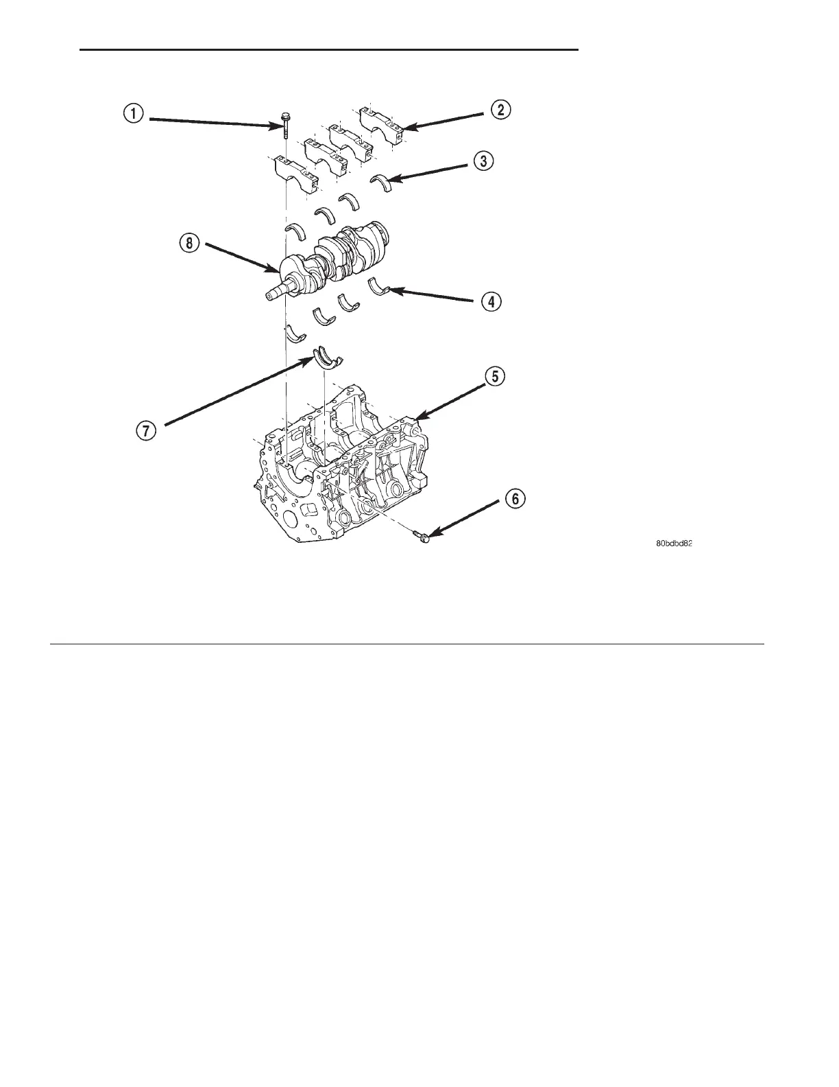
The crankshaft (Fig. 4) is constructed of a forged
micro alloy steel. A six throw, nine counterweight
crankshaft is supported by four select fit main bear-
ings with number two serving as the thrust washer
location. The six separate connecting rod throws are
an even-firing design which reduces torque fluctua-
tions while a torsional vibration damper is used to
control torsion caused vibration of the crankshaft.
Rubber lipped seals are used at front and rear. The
front seal is retained in the oil pump case and the
rear seal is retained in a block-mounted housing.
OPERATION
The crankshaft transfers force generated by com-
bustion within the cylinder to the flywheel or flex-
plate.
Fig. 4 Cylinder Block and Crankshaft
1 – MAIN CAP BOLT - VERTICAL
2 – MAIN CAP
3 – MAIN BEARING - LOWER
4 – MAIN BEARING - UPPER
5 – CYLINDER BLOCK
6 – MAIN CAP BOLT - HORIZONTAL
7 – CRANKSHAFT THRUST WASHER
8 – CRANKSHAFT
LH 3.2/3.5L ENGINE 9 - 77
DESCRIPTION AND OPERATION (Continued)