DIAGNOSIS AND TESTING
ENGINE DIAGNOSIS—INTRODUCTION
Engine diagnosis is helpful in determining the
causes of malfunctions not detected and remedied by
routine maintenance.
These malfunctions may be classified as either
mechanical (e.g., a strange noise), or performance
(e.g., engine idles rough and stalls).
Refer to the Service Diagnosis—Mechanical Chart
and the Service Diagnosis—Performance Chart, for
possible causes and corrections of malfunctions. Refer
to FUEL SYSTEM for the fuel system diagnosis.
Additional tests and diagnostic procedures may be
necessary for specific engine malfunctions that can-
not be isolated with the Service Diagnosis charts.
Information concerning additional tests and diagno-
sis is provided within the following:
• Cylinder Compression Pressure Test
• Cylinder Combustion Pressure Leakage Test
• Cylinder Head Gasket Failure Diagnosis
• Intake Manifold Leakage Diagnosis
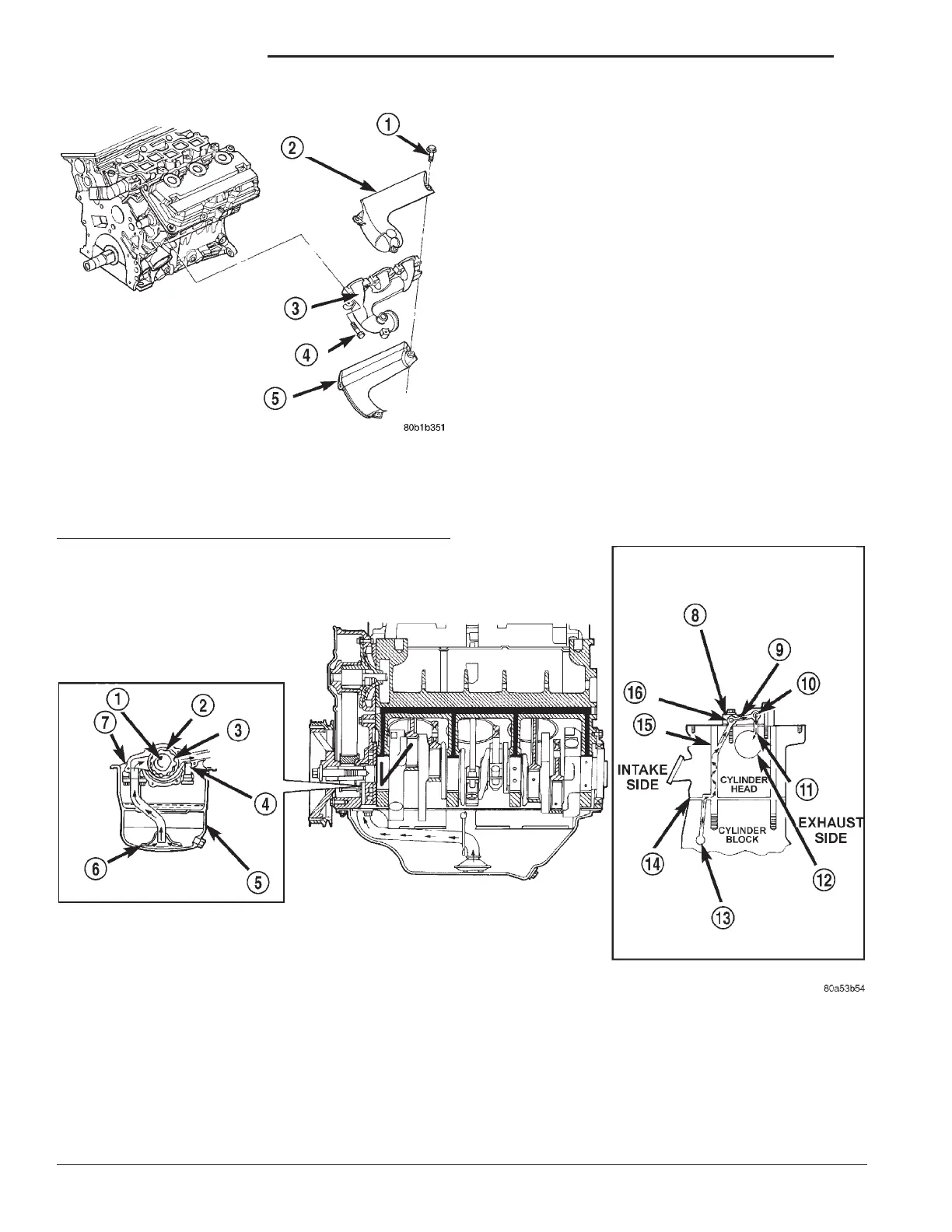
Fig. 10 Exhaust Manifold
1 – BOLT
2 – HEAT SHIELD
3 – EXHAUST MANIFOLD
4 – BOLT
5 – HEAT SHIELD
Fig. 11 Oil Lubrication System
1 – CRANKSHAFT
2 – OUTER ROTOR
3 – INNER ROTOR
4 – RELIEF VALVE
5 – OIL PAN
6 – OIL SCREEN
7 – OIL PUMP CASE
8 – OIL FLOWS TO ONLY ONE PEDESTAL AN EACH HEAD.
SECOND FROM REAR ON RIGHT HEAD AND SECOND
FROM FRONT ON LEFT HEAD.
9 – PEDESTAL DRILLED PASSAGE
10 – EXHAUST ROCKER SHAFT
11 – SHAFT/PEDESTAL DOWEL PASSAGE
12 – CAMSHAFT BEARING BORE
13 – CYLINDER BLOCK OIL GALLERY
14 – CYLINDER HEAD GASKET
15 – HEAD BOLT HOLE
16 – INTAKE ROCKER SHAFT
9 - 82 3.2/3.5L ENGINE LH
DESCRIPTION AND OPERATION (Continued)